EasyManua.ls Logo

INVT Goodrive350 Series

INVT Goodrive350 Series
341 pages
To Next Page IconTo Next Page
To Previous Page IconTo Previous Page
Loading...
Goodrive350 series high-performance multi-function inverter Appendix C
-307-
W1
W2
D1
H1 H2
6- ø13.0
W2
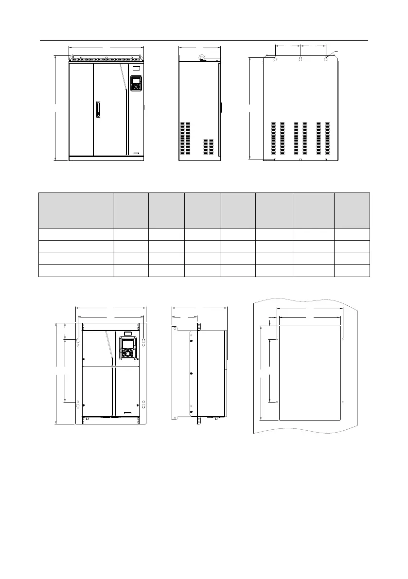
Fig C.16 Wall-mounting diagram of inverters of 660 V, 250 to 350 kW
Table C.4 Wall-mounting dimensions of 660 V inverters (unit: mm)
Inverter
specification
W1
W2
H1
H2
D1
Installation
hole
diameter
Fixing
screw
22kW45kW
270
130
555
540
325
7
M6
55kW132kW
325
200
680
661
365
9.5
M8
160kW220kW
500
180
870
850
360
11
M10
250kW350kW
680
230
960
926
380
13
M12
C.5.2 Flange installation dimensions
W1
H1
D1
W2
H2
98.0
D2
W2
W3W4
H4
H2
H3
Fig C.17 Flange installation diagram of inverters of 660 V, 22 to 132 kW

Table of Contents

Related product manuals