Goodrive350 series high-performance multi-function inverter Chapter 7
-219-
Chapter 7 Troubleshooting
7.1 What this chapter contains
The chapter tells users how to reset faults and check faults history. A complete list of alarms and fault
information as well as possible causes and corrective measures are presented in this chapter.
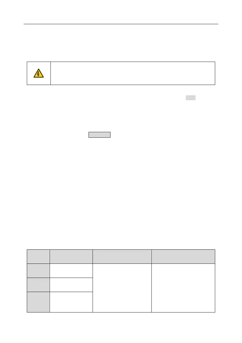
Only well-trained and qualified professionals are allowed to carry out the work
described in this chapter. Operations should be carried out according to the
instructions presented in Safety precautions.
7.2 Indications of alarms and faults
The fault is indicated by indicators (refer to the "Keypad operation process"). When TRIP indicator is
on, the alarm or fault code displayed in the keypad indicates the inverter is in exception state. This
chapter covers most of the alarms and faults, and their possible causes and corrective measures, if
users cannot figure out the alarm or fault causes, contact local INVT office.
7.3 Fault reset
Users can reset the inverter via STOP/RST key on the keypad, digital inputs, or by cutting off the
inverter power. After faults are removed, the motor can be start again.
7.4 Fault history
P07.27–P07.32 record the six latest fault types; P07.33–P07.40, P07.41–P07.48, and P07.49–
P07.56 record the running data of the inverter when the latest three faults occurred.
7.5 Inverter faults and solutions
When fault occurred, process the fault as shown below.
1. When inverter fault occurred, confirm whether keypad display is improper? If yes, contact INVT;
2. If keypad works properly, check the function codes in P07 group to confirm the corresponding
fault record parameters, and determine the real state when current fault occurred through
parameters;
3. Check the table below to see whether corresponding exception states exist based on the
corresponding corrective measures;
4. Rule out the faults or ask for help from professionals;
5. After confirming faults are removed, reset the fault and start running.
7.5.1 Details of faults and solutions
Inverter unit
Phase-U protection
Acceleration is too fast;
IGBT module is damaged;
Misacts caused by
interference; drive wires are
poorly connected ;
To-ground short circuit
occurs
Increase acceleration time;
Replace the power unit;
Check drive wires;
Check whether there is strong
interference surrounds the
peripheral equipment
Inverter unit
Phase-V protection
Inverter unit
Phase-W protection

 Loading...


