Goodrive350 series high-performance multi-function inverter Chapter 6
-217-
Detailed parameter description
Lower limit of
AO2 output
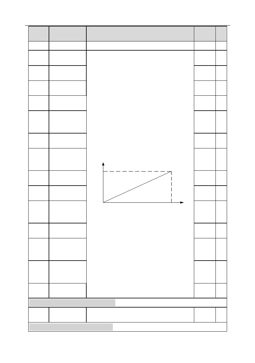
Above function codes define the relation between
output value and analog output. When the output
value exceeds the set max./min. output range, the
upper/low limit of output will be adopted during
calculation.
When analog output is current output, 1mA
corresponds to 0.5V voltage. In different
applications, 100% of output value corresponds to
different analog outputs.
Setting range of P26.38: -100.0%–P26.40
Setting range of P26.39: 0.00V–10.00V
Setting range of P26.40: P26.38–100.0%
Setting range of P26.41: 0.00V–10.00V
Setting range of P26.42: 0.000s–10.000s
Setting range of P26.43: -100.0%–P26.45
Setting range of P26.44: 0.00V–10.00V
Setting range of P26.45: P26.43–100.0%
Setting range of P26.46: 0.00V–10.00V
Setting range of P26.47: 0.000s–10.000s
Corresponding
AO2 output of
lower limit
Upper limit of
AO2 output
Corresponding
AO2 output of
upper limit
Lower limit of
AO3 output
Corresponding
AO3 output of
lower limit
Upper limit of
AO3 output
Corresponding
AO3 output of
upper limit
P28 group Master/slave control functions
P90 group Customized function group 1

 Loading...


