Goodrive350 series high-performance multi-function inverter Appendix A
-289-
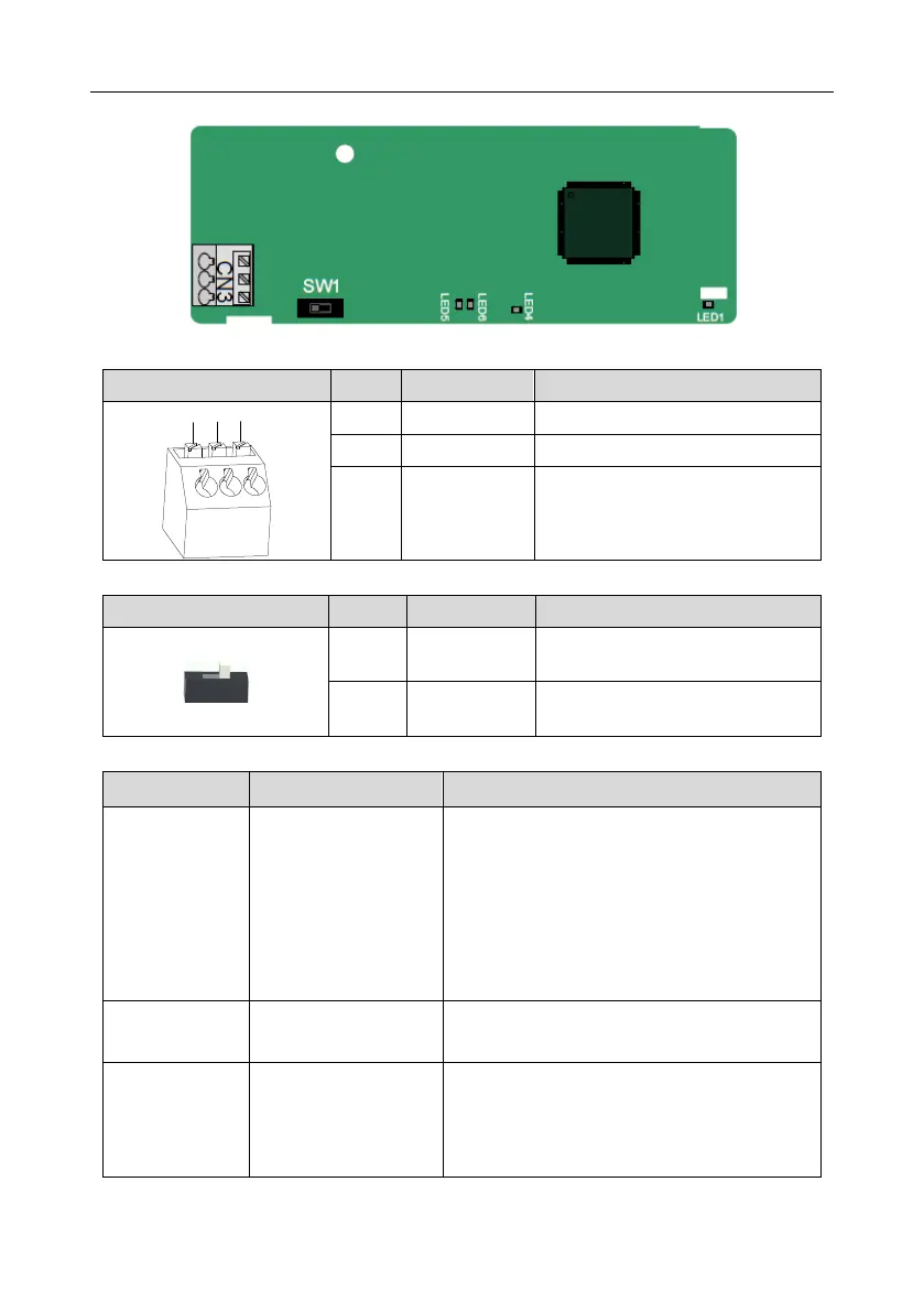
A.6.2 CANopen communication card––EC-TX505
The EC-TX505 communication card is user-friendly, adopting spring terminals.
CANopen bus high level signal
CANopen bus low level signal
Terminal resistor switch function description
CAN_H and CAN_L are not
connected to a terminal resistor.
CAN_H and CAN_L are connected to
a terminal resistor of 120 Ω.
Indicator definition
This indicator is on when the extension card is
establishing a connection with the control board;
it blinks periodically after the extension card is
properly connected to the control board (the
period is 1s, on for 0.5s, and off for the other
0.5s); and it is off when the extension card is
disconnected from the control board.
This indicator is on after the control board feeds
power to the communication card.
This indicator is on when the communication
card is in the working state.
It is off when a fault occurs. Check whether the
reset pin of the communication card and the

 Loading...


