iPECS eMG80
Hardware Description and Installation Manual Issue 1.0
72
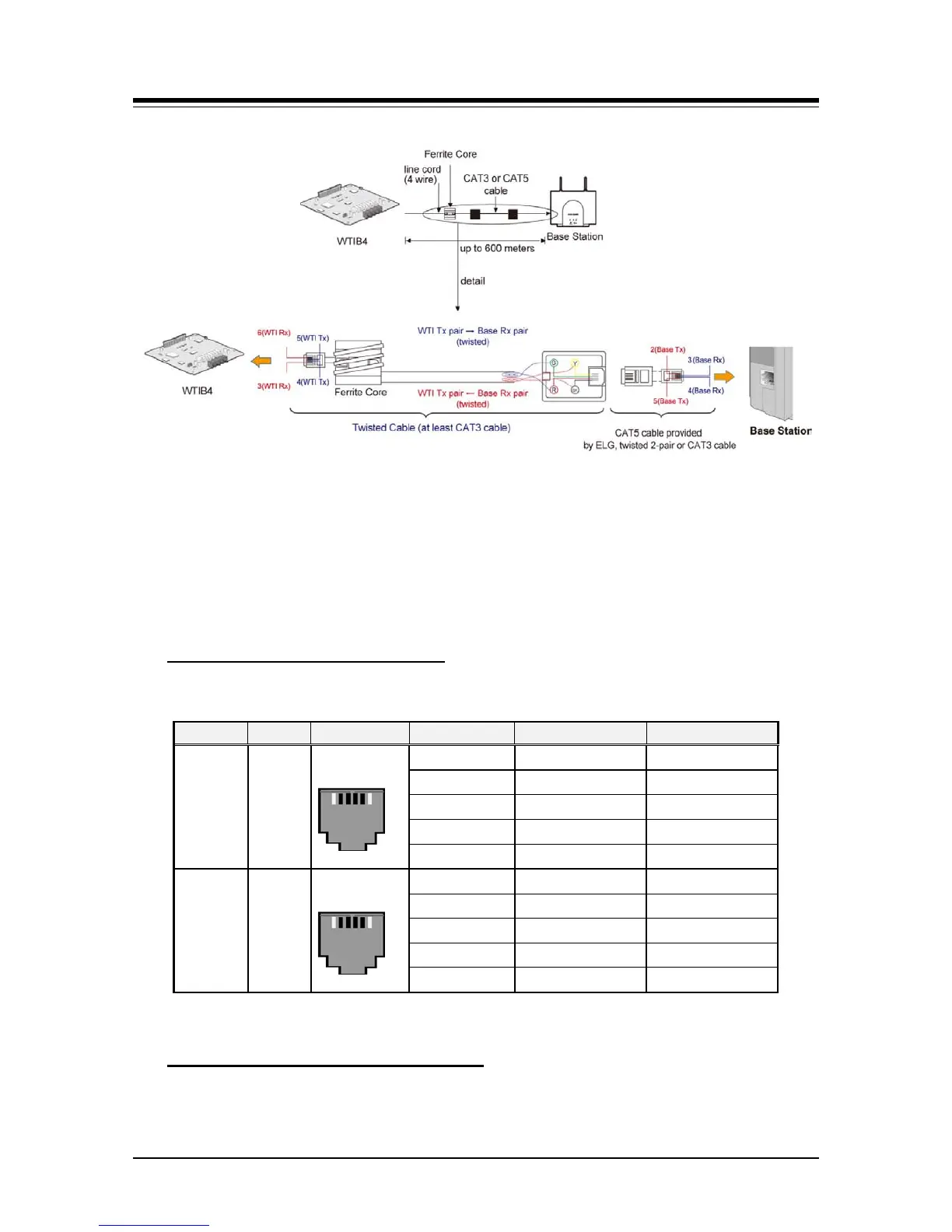
Figure 6.4.8-1 WTIB4 Wiring with Ferrite Core
CAUTION
All wiring between the WTIB4 and the GDC-600BE Base Station must use twisted pair
cable, use either Cat 3 or Cat 5 cabling. Use of untwisted pair wiring, even in short lengths
will cause faulty operation of the Base Station and the DECT handsets.
WTIB4 & GDC-600BE Connectors
Table 6.4.8-1 WTIB & GDC 600BE Modular Jack Wiring
Model Label Pin-out Pin Number Pin Assignment Function
WTIB4
WTI1
to
WTI4
1, 6
Unused/reserved
2
RX (GND) Receive Data
3
TX (+30V) Transmit Data
4
TX (+30v) Transmit Data
5
RX (GND) Receive Data
GDC-
600BE
MJ1
1, 6
Unused/reserved
2
Base TX (GND) Transmit Data
3
4
Base RX (+30v) Receive Data
5
Base TX (GND) Transmit Data
The WTIB4 incorporates routines to perform tests of the connection to each Base Station.
The Automatic Line Test can be performed is manually with Dip switches located on the
WTIB4 - Automatic Line Test Function
1 6
1
6


 To Next Page