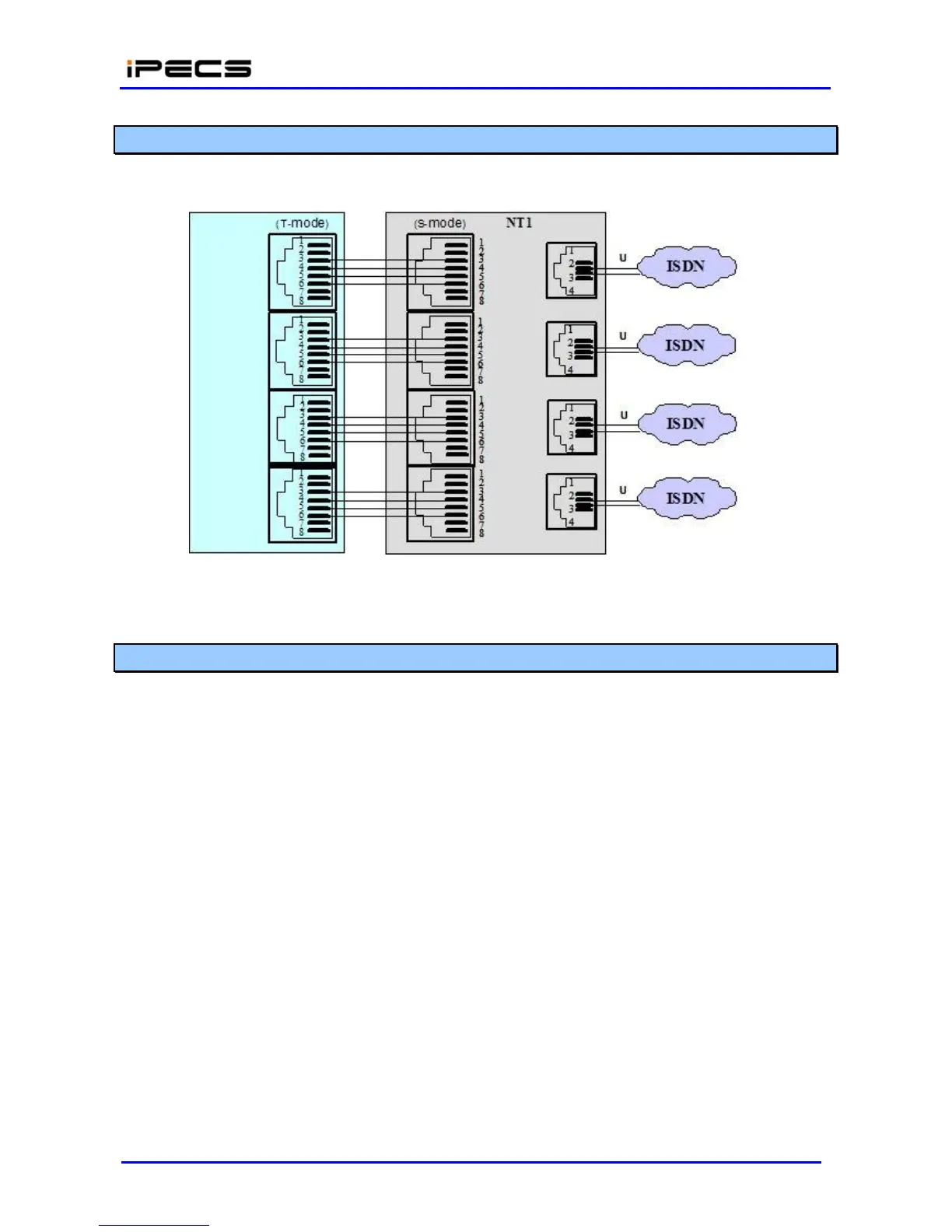
4.4.4.3 BRI Line Connections
BRI Line connectors should be wired to the telephone company termination point (‘T” Mode). The
connector pin assignments for the RJ-45 type jacks of BRI Ports are shown in Figure 4.4.4.3-1.
Figure 4.4.4.3-1 BRI Line Connector Configuration
4.4.4.4 LAN Connections
LAN connections are made by way of RJ-45 connectors on the front panel of each Module and in
the rear side of LIP Phones. These connectors are shown in Figure 4.4.4.4-1. Each connector
has
a
green Link/Activity LED and a yellow LAN speed LED, On for 100 Base-T.
The gateway Module “LAN” ports and the POE8 “UPLINK” ports as well as the LIP Phone LAN
port are terminated in the standard Media Dependent Interface (MDI) configuration shown in
Figure 4.4.4.4-1. The POE8 “X” LAN ports are terminated in the mating MDIX (crossover)
configuration as shown in the figure. The POE8 can provide power over the LAN with 48 VDC
across pin pairs 4&5 and 7&8. This configuration mates with the LIP Phone as shown in the figure.
Finally, the LIP-7016D/7024D/7024LD and LIP-8012D/8024D/8040L Phones are equipped with a
second LAN port, designated “PC” to connect a PC or similar device allowing a shared LAN
infrastructure. This connector is terminated in the MDIX configuration mating to a typical PC with a
straight cable.