All LAN wiring should use Category 5 Unshielded Twisted Pair (CAT 5 UTP) cable. No single run
of LAN cable should exceed 100 meters (about 330 feet).
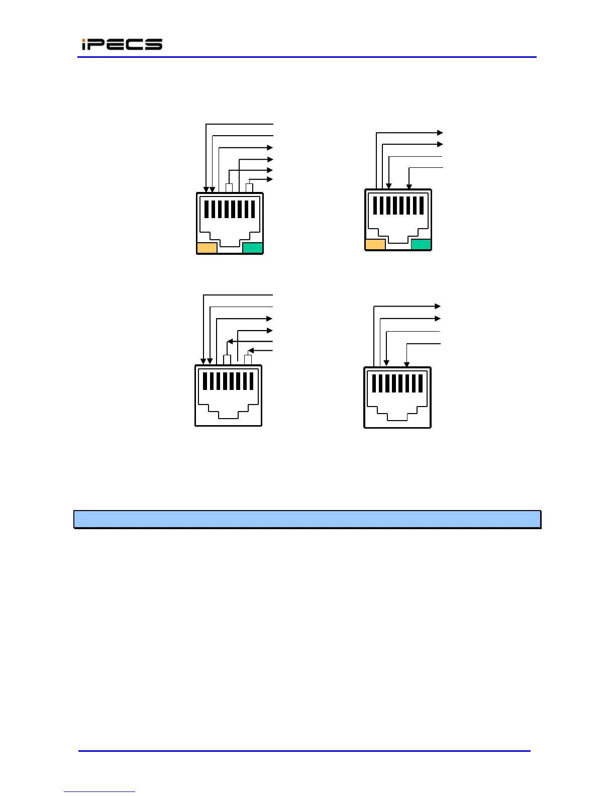
RX+
RX-
TX+
TX-
DC
+
DC-
TX+
TX-
RX+
RX-
Yellow LED
On = 100 M
Off = 10 M
1 2 3 4 5 6 7 8
1 2 3 4 5 6 7
8
Green LED
On = Link+ACT
Flash = Activity
PoE8 1x~8x PORT
EIA 568A (MDIX) w/Pwr
TX+
TX-
RX+
RX-
DC+
DC-
Gateway & PoE8 UPLINK
EIA 568B (MDI)
RX+
RX-
TX+
TX-
1 2 3 4 5 6 7
8
1 2 3 4 5 6 7 8
IP Phone LAN port
EIA 568B (MDI) w/Pwr
IP Phone PC port
EIA 568A (MDIX)
Figure 4.4.4.4-1 Pin Assignments of LAN Connector (RJ-45)
4.4.4.5 LAN Wiring Structure
The LAN wiring architecture used for connecting iPECS Modules to the LAN is dependent upon
several factors including:
Shared or iPECS only LAN infrastructure
External VoIP calling requirements
New or existing voice and/or data installation
Remote LAN power or local AC power for iPECS Phones
The “PC” LAN port of equipped LIP Phones can be connected to the user’s desktop using a
standard LAN cable terminated with RJ-45 LAN jacks. The LAN jack is wired to an Ethernet switch,
which has access to the LIK-MFIM50A/B, other iPECS Modules and LIP Phones. This
connection can be through a connection to the same switch or by an indirect connection through
multiple switches.