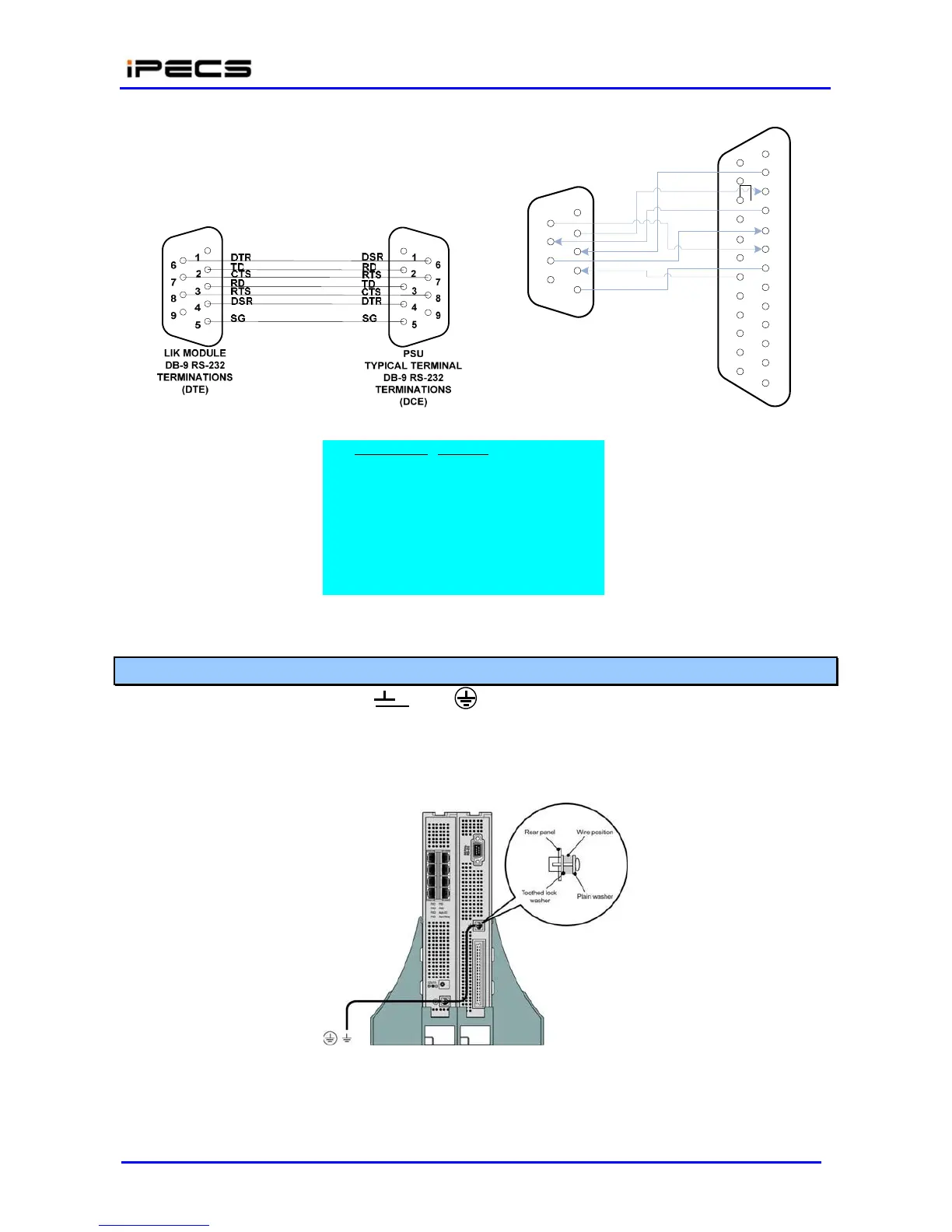
LIK
MODULE
DB-9
RS-232
TERMINATIONS
1
DTR
6
TD
2
CTS
7
RD
3
RTS
8
DSR
4
9
SG
5
1
TD 14
2
RD
15
3
RTS
16
4
CTS
17
5
DSR
18
6
SG
19
DTR
7
20
8
21
9
22
10
23
TYPICAL
TERMINAL
11
24
DB-25
RS-232
12
TERMINATIONS
25
13
Designation. Function
TD Transmitted Data
RD Received Data
RTS Request To Send
CTS Clear To Send
DTR Data Terminal Ready
DSR Data Set Ready
Figure 4.4.4.6-1 RS-232 DB-9 Pin-outs
4.4.4.7 Module Grounding
As shown in Figure 4.4.4.7-1, a “ ” or “ “ screw is located on the rear panel of each
Module. For proper operation and code compliance, the grounding screw should be connected to a
known protective earth ground using a #12 AWG or larger UL-1015 type copper wire. The wire
should be located between the toothed lock washer and the plain washer. Note that when using
the cabinet, a separate ground connection to the individual Modules is not required.
Figure 4.4.4.7-1 Module Grounding