| Assembly and installation
54
YLS-K
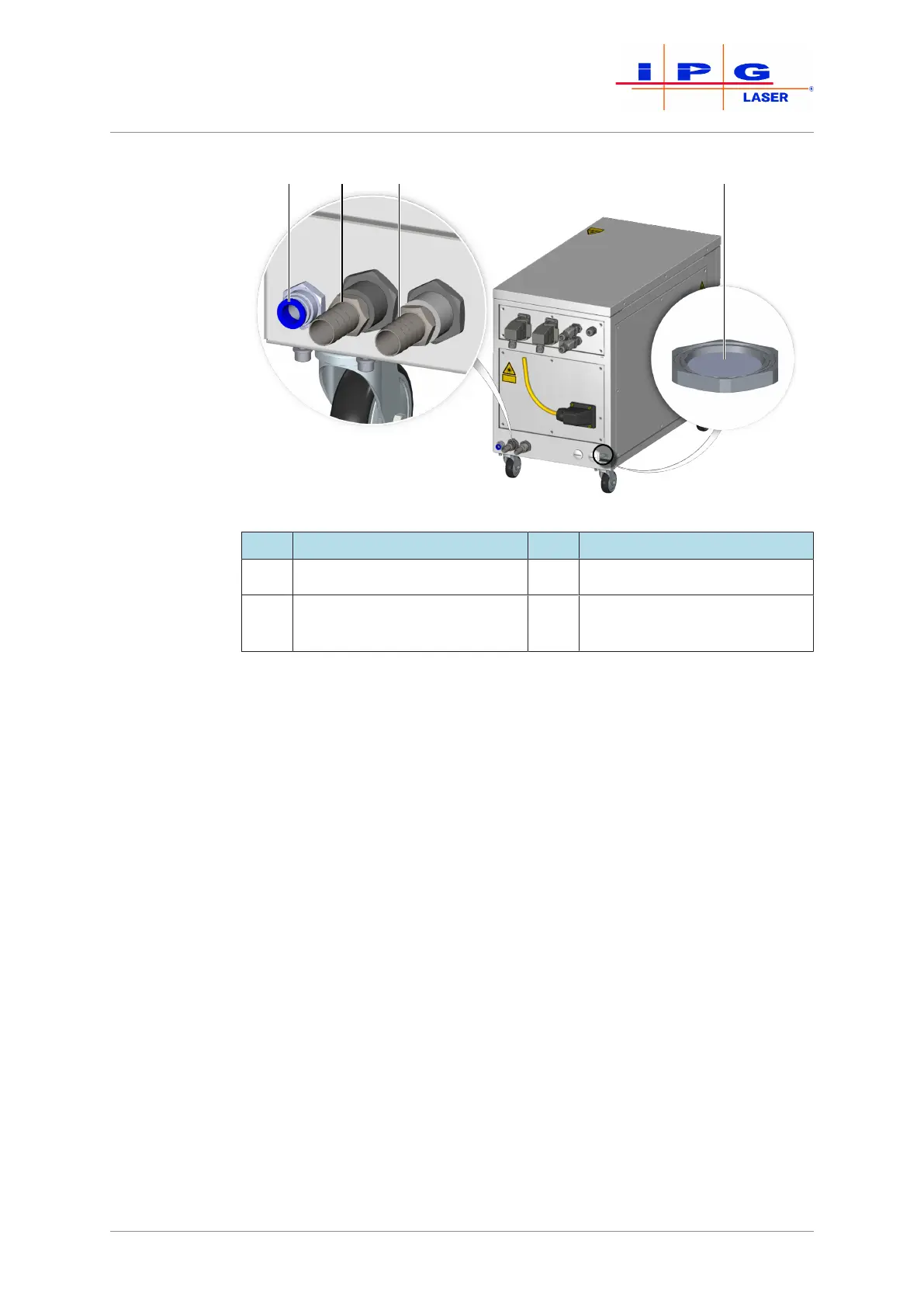
Figure23: Water connections
Item Designation Item Designation
1 Condensate drain 3 Laser circuit water inlet
2 Laser circuit water outlet 4 Water drain with water-solu-
ble membrane
The product is equipped with a water drain with a water-soluble mem-
brane in the cabinet bottom. In the case of a leakage inside the laser, the
membrane dissolves and the water can flow out through the water
drain.
ð When connecting the water supply, take care that the water drain
does not get wet as this could cause the membrane inside to dis-
solve. The absence of the membrane impairs the seal of the cabi-
net so that the correct microclimate inside the cabinet can no
longer be guaranteed.
Connecting the
water supply
1. Connect the hoses of the tap water supply to the laser circuit con-
nections according to the designation. Note the direction of water
flow.
2. Ensure sufficient cooling of the process optics and the fiber con-
nector.
The fiber connector is equipped with temperature sensors that trigger an error in
the laser if the upper limit is exceeded (see supplied technical data).