| Safety
24
YLS-K
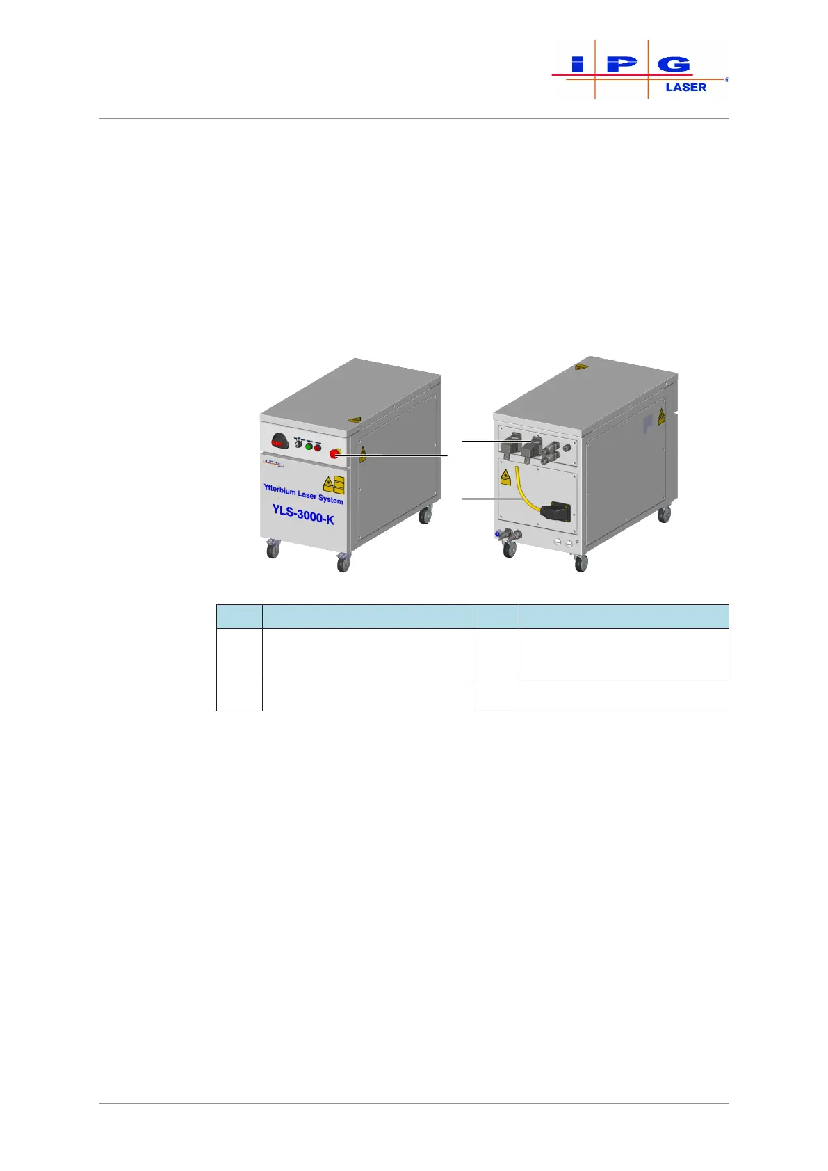
2.10 Safety equipment
The danger zone is secured by safety features. The safety features con-
sist of:
• E-Stop button
• External E-Stop
• Fiber break monitoring
The figure below shows the positions of the safety features on the prod-
uct.
Figure1: Safety features
Item Designation Item Designation
1 Safety and control interface
XPIF*
3 Fiber break monitoring
2 E-Stop button
*For simplification, the safety and control interface XPIF is referred to below as the
safety interface.
The status of the individual safety features is indicated in the LaserNet
software in the Status tab [}93] and the Alarms tab [}95].
The triggering of a safety feature has the following effect:
1. The corresponding safety circuit is opened.
2. The main power supply is shut down.
3. The laser emission is shut down.
Switching on the
main power sup-
ply
In order to switch on the main power supply, all safety circuits must be
closed and the safety control of the product must be reset.
ð Close all safety circuits.
If all safety circuits are closed, the safety control of the product can be
reset manually.