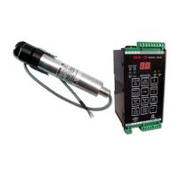
IRIS MODEL 700/800 APPLICATION MANUAL
PAGE 11
shown in Table 1 being loaded and stored in EEPROM:
In the Model 700, if the AUTO SET LED is on when
the LOAD FACTORY DEFAULTS key is pressed,
“CF” will be displayed. Press the LOAD FACTORY
DEFAULTS key again to confirm your request, or press
RESET to abort your request. If you load factory de-
faults, the AUTO SET LED will be turned off.
The Model 800 does not have an automatic mode in
which it calculates set points, so confirming an over-
write of calculated set points is not part of the Model
800 applications software.
SETTING FFRT – MODELS 700 AND 800
You may press the FFRT key to change the Flame Fail-
ure Response Time over the range one to three sec-
onds, using the increase and decrease keys on the Model
700, or from the application software or setup program-
mer available for the Model 800. These changes, how-
ever, are not live; they take effect only if the STORE
key is pressed. FFRT values do not relate to the RE-
LAY ON SET POINT and RATIO values, so if the
AUTOSET LED is on in the Model 700, confirmation
is not needed to change the FFRT setting.
0-20 MA/4-20 MA OPTION –
MODELS 700 & 800
An analog output current is provided for operating a
remote meter or other instrumentation. The load resis-
tance should not exceed 360 Ohms for the Model 700
or 100 Ohms for the Model 800. The resistance can be
chosen to give the desired voltage swing. For example,
if 2V is desired for a 20 mA output, a 100 Ohm resistor
would be used.
The analog current output can range from 0 to 20
milliamps, or from 4 to 20 milliamps. A change can be
made by pressing the 0-20 MA/4-20 MA OPTION key
and using the INCREASE and DECREASE keys. This
change can also be made from the setup programmer
or application software for the Model 800. The display
will show “02” or “42” as appropriate. This function is
live; the operative range changes as soon as the dis-
played selection is changed. But, as with the other func-
tions, you should press STORE for a change to be stored
in the signal processor’s EEPROM.
The analog current output is scaled according to the
RELAY ON setting. It is scaled so that, if the counts
coming in are at a count rate equal to the RELAY ON
setting, the current output is approximately 13 MA when
the range selected is 0-20 MA, and about 14.6 MA when
the range selected is 4-20 MA.
Note that the actual maximum level for the current out-
put is 19.8 MA. It is slightly less than 20 MA so that a
data sampling system will not switch ranges when the
current reaches a maximum.
Confirmation is not requested if the 0-20/4-20 setting
is changed when the AUTOSET LED is on.
LOCKOUT OR FAULTY VH INDICATION
If the viewing head produces any pulses during the last
one third of the self-check time, the relay will immedi-
ately drop out, the display will show “LO” (lockout), and
the FAULT LED will flash on and off rapidly. On the
Model 800, this will be indicated by the green LED
flashing rapidly. Exit lockout by pressing RESET. If a
pulse or pulses come in during the last one third of the
self-check time while the automatic data sampling is tak-
ing place, the automatic process will be aborted, the relay
will be opened if it was closed, the display will show “LO”
)lockout), and the FAULT LED will flash on and off rap-
idly. Press RESET to exit this. If a viewing head is dis-
connected, the display will show “L1.” Reconnect the
viewing head and press RESET.
PANEL LOCK
A pattern of key presses will result in the panel being
locked so as to block the storage of any changes to the
values stored in the signal processor. With the panel
locked, values may be examined, but the signal pro-
cessor will not respond to the STORE key.
The panel should be locked after the set points are set.
Contact the factory to obtain the procedure to lock or
unlock the panel.
The Model 800 processor does not allow any values to
be changed other than by using the setup programmer
or application software.
PANEL LOCK WITH NO VH CONNECTED
When the signal processor is working with an intelli-
gent viewing head, it expects to have continuous com-
munication with the viewing head. If the viewing head
is disconnected, communication is lost, the display is
made inoperative, and no settings can be examined or
changed. Reconnect the viewing head and cycle power
to correct this condition.
WORKING WITH OLDER UV VIEWING
HEADS
When the signal processor has been set up with an older
UV viewing head without communications, the settings
may be viewed and changed whether or not the view-
ing head is connected. But, if the viewing head is

 Loading...