IRIS MODEL 700/800 APPLICATION MANUAL
PAGE 5
IR DETECTOR
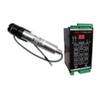
The models S702 and S802 viewing heads use the same
InGaAs (Indium Gallium Arsenide) photodiode used in
our S511, S550, and S552 viewing head models. This
IR photodiode responds to IR in the 950nm to 1710nm
range (1/2 intensity points). The use of IR flicker instead
of IR intensity in the viewing head has many advantages
- one being that the viewing head does not respond to
glowing refractory in the furnace. The main advantage
comes from the fact that high frequency flicker is pro-
duced in the turbulent part of the burner flame, close to
the root where combustion takes place. When this part
of the flame is monitored, and when the viewing head
responds only to the high frequency flicker, the turbulent
part of the flame stands out from bright, but less turbu-
lent, portions of other flames. The standard S702, S702-
PF and S802 viewing heads respond to flicker frequen-
cies above 33 Hz; the S702-HF, S702-HF-PF and the
S802-HF viewing heads respond to flicker frequencies
above 155 Hz.
UV DETECTOR
The S706, S706-PF and S806 viewing heads use the
same UVtron tube for UV sensing that we have been
using on our other UV-sensitive viewing heads. The
UVtron responds only to short wavelength ultraviolet
radiation in the 185-260nm range. This radiation is a
direct result of the combustion process as oxygen com-
bines with hydrocarbons in the fuel in the blue part of
the flame. The yellow part of flames, and the back-
ground radiation from tubes or firebrick, do not emit
UV radiation. So, where viewing heads can be aimed
at the root of burner flames, UV monitoring provides
excellent discrimination between flames in adjacent
burners in multiburner applications.
SELF-CHECKING
There is a small processor in both the IR and UV view-
ing heads, so it is possible that this processor could fail
and produce erroneous viewing-head pulses. The self-
check circuitry guards against this. There are several
tasks that require intelligent interaction between the view-
ing heads and the signal processor. If all of these inter-
actions do not occur properly, the viewing head will not
send pulses back to the signal processor and the flame
relay will open.
Verifying the validity of the gain code received is one of
the tasks performed by the processor in the IR and in the
UV viewing heads. The self-check pulse from the signal
processors is a 100ms-wide, 20V to 24V pulse with two
“notches” or breaks in it. The position of each of the two
notches communicates a gain code of one to nine plus
parity to the viewing head. The viewing head sends
back an ID pulse in the first half of the 100ms self-
check time. One viewing head expects to receive data
with one parity and the other expects to receive data
with the other parity. If a viewing head does not re-
ceive its correct parity plus the gain code once per sec-
ond, it produces no output pulses.
There is also intelligent interaction between the older S706
viewing heads, which did not have the gain-change fea-
ture from the signal processor. The processor in the S706
viewing head monitors the 100ms width of the self-check
pulse coming from the signal processor. If the pulse is
not the correct width the viewing head produces no out-
put pulses. Also, if the signal processor receives any pulses
back from the viewing head during the last half of the
100ms self-check time, it assumes that a processor failure
has occurred in the viewing head, opens both relays, and
displays “LO” (lockout).
INTERNAL PARAMETER STORAGE
Set point values and other parameters plus error- check-
ing codes are stored in EEPROM (Electrically Eras-
able Programmable Read Only Memory) in both the
Model 700 and Model 800 signal processors. This data
is then error-checked when it is read at power up. For
the Model 700AC and Model 700DC, if the data does
not match exactly what was stored, the signal proces-
sor discards all data, displays “EE”, and loads factory
defaults. The RELAY ON SET POINT is set to 31.
Since the display cannot go this high, the flame relay
cannot be energized. The signal processor can be reset
by changing the RELAY ON SET POINT to a reason-
able value or by pressing LOAD FACTORY DE-
FAULTS. For the Model 800, an internal EEPROM
failure is indicated by a rapidly blinking green LED.
Pressing the RESET button will clear the rapidly blink-
ing LED but the Relay-on set point will remain set at
31. The Relay-on set point can only be changed by con-
necting a programmer or computer to the model 800
signal processor and loading factory defaults, or chang-
ing the relay on set point of 31 to a reasonable value. In
any event, one should be suspicious of a signal proces-
sor that has failed in this way.
Note that information about the type of viewing
head which was last used is also stored in
EEPROM. If a Model 700 signal processor
is powered up with a different type of viewing
head, the signal processor discards the
previous set-point data and loads factory
defaults, except the RELAY ON SET POINT

 Loading...