/30
IRMA MATRIX Door Clear option | Mounting and operating instructions
released
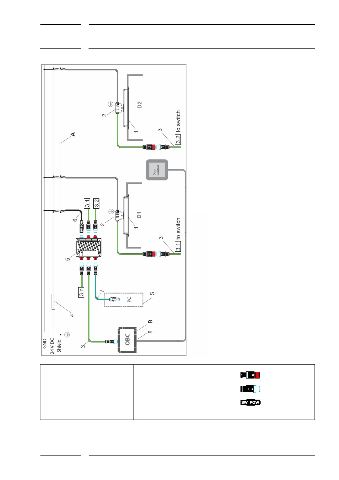
1 IRMA MATRIX sensor (built-in version)
2 sCON-S-Connector for sCON-S-ETH-22-
Kn-1-2m Ethernet connection
3 M12 system Ethernet cable
K-M12CAT5-XX-xm
4 Fuse 10A, fast
5 M12 switch: Switch-M12-5Port-eCon
6 Power cables for switch; K-Switch-
Power (=K2); or SAC-4P-5,0-28R/FS SCO RAIL
7 KQ-M12CAT5-RJ45-01-xm adapter cable for PC
connection for support services
8 Still to be defined
A Distribution of the on-board power supply to
each door for connecting sensors and switches.
The distribution of the on-board power supply to
each door is not part of the standard scope of
supply of iris-GmbH!
B Connection to On-Board Computer/Unit PC
connection for support services
D1, D2 Function area 1 and 2
M12 female
connector, ETH type
M12 male
connector, ETH type
M12 female
connector, ETH type, 4-pole, A-
coded (K-Switch-Power)
Fig. 3: Wiring diagram for Ethernet using sCON-S