13
1 2 3 4 5 6 7 8 9 10
11 12 13 14 15 16 17 18 19 20
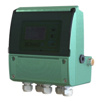
LED INTERPRETATION
PERMANENT LIGHT: initialization
FLASHING LIGHT (1 sec.): normal function
FLASHING LIGHT (<1 sec.): alarm on
The LED signals the alarm status only if the display shows one of
the suitable visualization screens
FLAGS INTERPRETATION
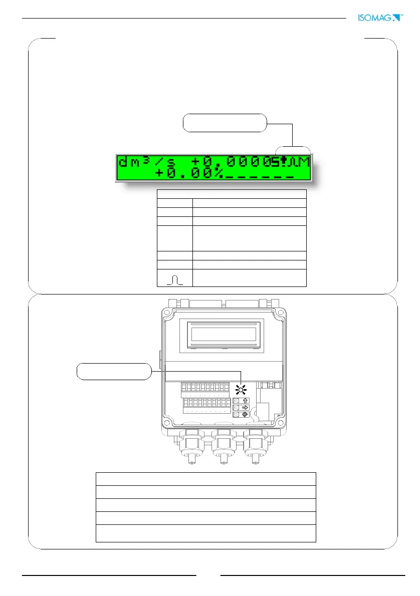
FLAG DESCRIPTION
M Alarm max activated
m Alarm min activated
!
- Interruption coils circuit
- Signal error
- Empty pipe
C Calibration running
S Simulation
Pulse output saturation (reduce
TIME PULSE )
At ‘Power on’ of the converter, the user will see the following display screen. In the
top right hand corner there may be a range of symbols. The symbols can be
interpreted from the table below. Interpretation of the flashing LED can be made
from the LED interpretation table at the bottom of this page.
DISPLAY FLAGS AND LED WARNING INTERPRETATION