Do you have a question about the ISOMAG ML 110 and is the answer not in the manual?
General guidelines for safe installation, maintenance, and use of the converter.
Instructions for proper disposal of the product and its parts according to regulations.
Indicates actions that can result in injury or a safety hazard if not performed correctly.
Indicates actions that can result in incorrect operation or destruction of the device if not performed correctly.
Indicates actions that can have an indirect effect on operation or trigger unexpected responses.
Details on power supply voltage, frequency, and maximum power consumption.
Specifies altitude and humidity ranges for converter operation.
Defines the acceptable minimum and maximum operating temperatures in Celsius and Fahrenheit.
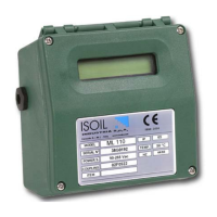
Lists the technical information found on the device's data plate.
Physical dimensions and weight for the PA6 housing compact version.
Physical dimensions and weight for the PA6 housing separate version.
Required torques for cover screws, cable glands, and IF2 cap for IP degree.
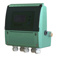
Physical dimensions and weight for the aluminum housing compact version.
Physical dimensions and weight for the aluminum housing separate version.
Required torques for cover screws, cable glands, and IF2 cap for IP degree.
Emphasizes the importance of correct grounding for safety and equipotentiality.
Details on connecting the power supply for PA6 and Aluminum housings.
Identifies power supply, IF2 socket, signalling LED, and keyboard.
Wiring diagram for connecting the PA6 converter to the sensor in separate version.
Identifies power supply, IF2 socket, signalling LED, keyboard, and shield.
Wiring diagram for connecting the aluminum converter to the sensor in separate version.
Diagram showing digital input configuration with external power supply.
Diagram showing digital input configuration with internal power supply.
Explains auto-calibration, reset totalizers, block totalizers, and range change operations.
Wiring details and specifications for the on/off output at 1250Hz.
Wiring details and specifications for the 4-20mA output.
Explains the meaning of different flags displayed on the converter screen.
Describes the meaning of the LED indicator's permanent and flashing lights.
Details on how to use the keypad for navigation and function selection.
Information on programming converters without a keyboard using ISOCON software.
Illustrates the sequence of display screens shown when the transmitter powers on.
Explains how to enable currency function for totalizers.
Describes the 5-digit display for flow rate units and maximum representable values.
Explains how measure unit representation depends on sensor flow rate and diameter.
Details on the L2 access code for enabling functions and security levels.
Provides the default L2 access code for the converter.
How to access the Quick Start menu upon powering up the converter.
Explanation of setup functions for batching, regulation, and flow measurement.
Table of filter settings for different sampling rates.
How to configure the converter using the ISOCON Windows software.
Ways to access configuration menus using the converter's keypad.
Step-by-step guide to change the full scale value using the Quick Start menu.
Step-by-step guide to change the full scale value using the Main Menu.
Configuration parameters related to the sensor, like nominal diameter and calibration data.
Parameters for setting full scale values, units, and decimal places for ranges.
Settings for measure filters, low flow threshold, and energy saving functions.
Configuration for maximum/minimum flow rate alarms and output failure values.
Settings for totalizer resets and autozero calibration external command.
Selection of functions for digital outputs 1 and 2, including pulse and frequency choices.
Configuration for communication protocols, baud rate, parity, and address.
Settings for language, display update rate, contrast, and currency visualization.
Options for converter calibration, self-test, and flow rate simulation.
Access to level 2 access code, factory/user presets, and calibration error settings.
Detailed explanation of sensor-related functions like electrode cleaning and autozero calibration.
Detailed explanation of scale setting functions, including units and numeric values.
How to set measure units and decimal places for volume measurements.
Configuration of pulse output for channels 1 and 2, including value and duration.
Explanation of the main frequency filter for electrical noise reduction.
Details on the slow length measure filter and its effect on response time.
Details on the fast length measure filter, available via ETP.
Visual representation of instrument response with different filter settings.
Configuration for automatic scale change and energy saving features.
Setting the 4-20mA output value during failure conditions (empty pipe, ADC error).
Setting the frequency output value during failure conditions.
Enabling totalizer resets and autozero calibration via on/off input.
Selection of functions for digital outputs 1 and 2, including pulse and frequency choices.
Setting the current output (4-20mA or 4-22mA) scale zero and full scale.
Setting conversion factors and currency for flow rate totalizers.
Procedure for calibrating the meter using the diagnostic menu.
Performing an automatic meter test cycle for diagnosing issues.
Lists alarm messages, their causes, and recommended corrective actions.
Provides a table of error codes, descriptions, and actions to take for anomalies.
Instructions and form for returning instruments for repair or calibration.
Guidance on testing sensor isolation and continuity before returning.
Fields for entering sensor/converter serial numbers and failure descriptions.
Confirmation of sensor cleaning and details about the measuring medium.
Declaration of compliance for the ISOMAG ML 110 converter and sensor models.
Lists the European norms and CE directives the product complies with.
Head office and service contact details for Isoil Industria spa.
Contact details for the official dealer in the Netherlands (U-F-M B.V.).
| Type | Media Converter |
|---|---|
| Model | ML 110 |
| RJ45 Ports | 1 |
| Fiber Ports | 1 |
| Fiber Connector | SC |
| Wavelength | 1310 nm |
| Operating Temperature | 0°C to 50°C |
| Power Input | 5V DC |
| Humidity | 5% to 90% non-condensing |