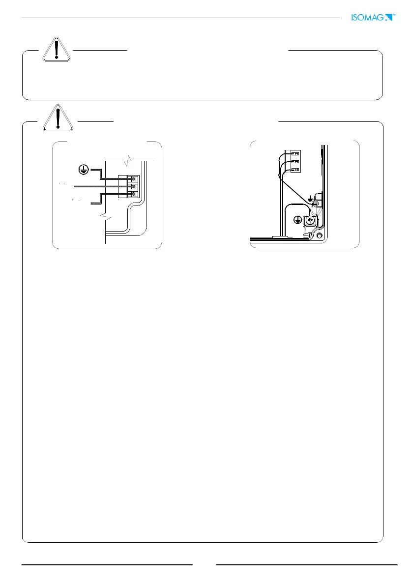
8
L
(-)
N
(+)
M3
M3
ELECTRICAL CONNECTIONS
ALWAYS ensure that the converter and the sensor are grounded (earthed) correctly. The
grounding of the sensor and converter ensures that the equipment and liquid are
equipotential.
Before connecting the power supply, verify that the mains voltage is within the limits
indicated on data plate.
For the connections use only approved conductors, with fire-proof properties, whose
section varies from 0.25mm
2
to 2.50mm
2
, based on distance/power; additionally fix
the power supply wires with a additional fastening system located close to the
terminal.
The power supply line must be equipped with an external protection for overload
current (fuse or automatic line breaker).
Provide in close proximity the converter a circuit breaker easily accessible for the
operator and clearly identified; whose symbols must conform to the electrical safety
and local electrical requirements.
Ensure that the component complies with the requirements of the standard for
electrical safety distance.
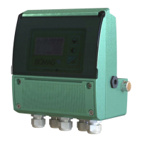
Check chemical compatibility of materials used in the connection security systems in
order to minimize electrochemical corrosion. In the aluminum housing it should
avoid direct contact between the ground connection cable and the aluminum
housing. It is therefore recommended to connect the safety ground cable, by placing
it between the washer and the metal bracket on the related terminal or use an
eyelet terminal crimped on the ground protection cable.
The sensor, hardwired inputs and outputs are connected to the converter through
terminal blocks located inside the converter.
To locate the terminal block loosen the 4 screws on the front cover. When the front
cover is lifted, the terminal block is visible. The terminal block is the hardwire
connection of the converter to external equipment, including the sensor.
The following pages give informations on the terminal block numbering, and the
respective connecting of the sensor cables, and inputs/outputs.
CONVERTER POWER SUPPLY
PA6 HOUSING
ALUMINUM HOUSING