ARMY TM 9-2815-254-24
AIR FORCE TO 36G1-94-2
1-1
3-1
3-2
3-3
3-4
3-5
3-6
3-7
3-8
3-9
3-10
3-11
3-12
3-13
3-14
3-15
3-16
3-17
3-18
3-19
3-20
3-21
3-22
3-23
3-24
3-25
3-26
3-27
3-28
3-29
3-30
3-31
3-32
3-33
3-34
3-35
3-36
3-37
3-38
3-39
3-40
3-41
3-42
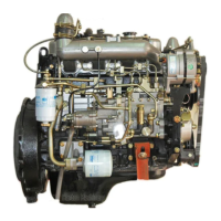
Engine Components
....................................................
1-4
Thermostat and Housing
...............................................
3-16
Water Pump
..........................................................
3-20
Fuel Filter Assembly...............................................
. . . . 3-23
Fuel Injectors and Piping............................................
. . . 3-26
Fuel Injector Spay Pattern..............................................
3-30
Top Dead Center.......................................................
3-32
Fuel Feed Pump and Timer Assembly
......................................
3-34
Fuel Injection Pump Assembly
............................................
3-35
Attaching Coupling (Typical)..............................................
3-36
lnserting Tappet Holder (Typical)
..........................................
3-36
Removing screw Plug (Typical)
..........................................
3-37
Removing coupling (Typical).................................................
3-37
Removing Tappet Holder (Typical).
............................................
3-38
Removing Tapped (Typical)
...................................................
3-39
Removing Delivery Valve
.....................................................
3-40
Removing Plunger Barrel....................................................
3-41
Plunger Helix..
.............................................................
3-43
Checking Plunger and Barrel
Movement
.......................................
3-44
Delivery Valve..............................................................
3-44
Checking Plunger and Barrel for Damage
3-45
......................................
Tappet
.....................................................................
3-45
Lower Spring Seat..........................................................
3-46
Camshaft
..................................................................
3-46
camshaft Bearings..........................................................
3-47
Bearing Removal...........................................................
3-47
Feed Pump Tappet
..........................................................
3-48
Feed Pump Plug
............................................................
3-49
Checking Sleeve Pinion Movement
............................................
3-51
lnserting Plunger
............................................................
3-51
lnserting Tappet
.............................................................
3-52
Measuring Device Installed (Typical)...........................................
3-55
Feed Pump Test
.............................................................
3-59
Priming Pump Test
..........................................................
3-60
Capacity Test
...............................................................
3-61
Feed Pump Pressure Test
....................................................
3-62
Air Tightness Test
...........................................................
3-62
RemovaI of Mechanical Governor.............................................
3-64
oil Filter
...................................................................
3-70
oil Piping
..................................................................
3-72
Oil Pan Assembly...........................................................
3-73
Oil Pump Assembly
.........................................................
3-75
Oil Pump Inspections........................................................
3-77
iv

 Loading...