Inspection and Installation
3. Refer to the wiring diagram, and use armored twisted-pair cables to connect
the remote sense terminals and the equipment under test.
4. Thread the red and black test cables and sense cables through the output
terminals cover and install the cover.
5. Connect the other end of the remote sense cables and the red and black ca-
bles to the DUT. The positive and negative poles must be properly con-
nected and fastened when wiring.
6. Power on the instrument and turn the sense function on. Please refer to
4.2.3 Set the Sense Function State for the detailed operations.
2.6 Connect the Communication Interface
This series power supply comes standard with two communication interfaces:
USB and LAN, and supports two optional communication interfaces: GPIB,
RS232. You can choose one of them to communicate with your computer. For
details, see 1.8 Models and Options.
The reserved communication card installation slot is on the rear panel of the in-
strument. Users can install it directly after purchasing the communication card.
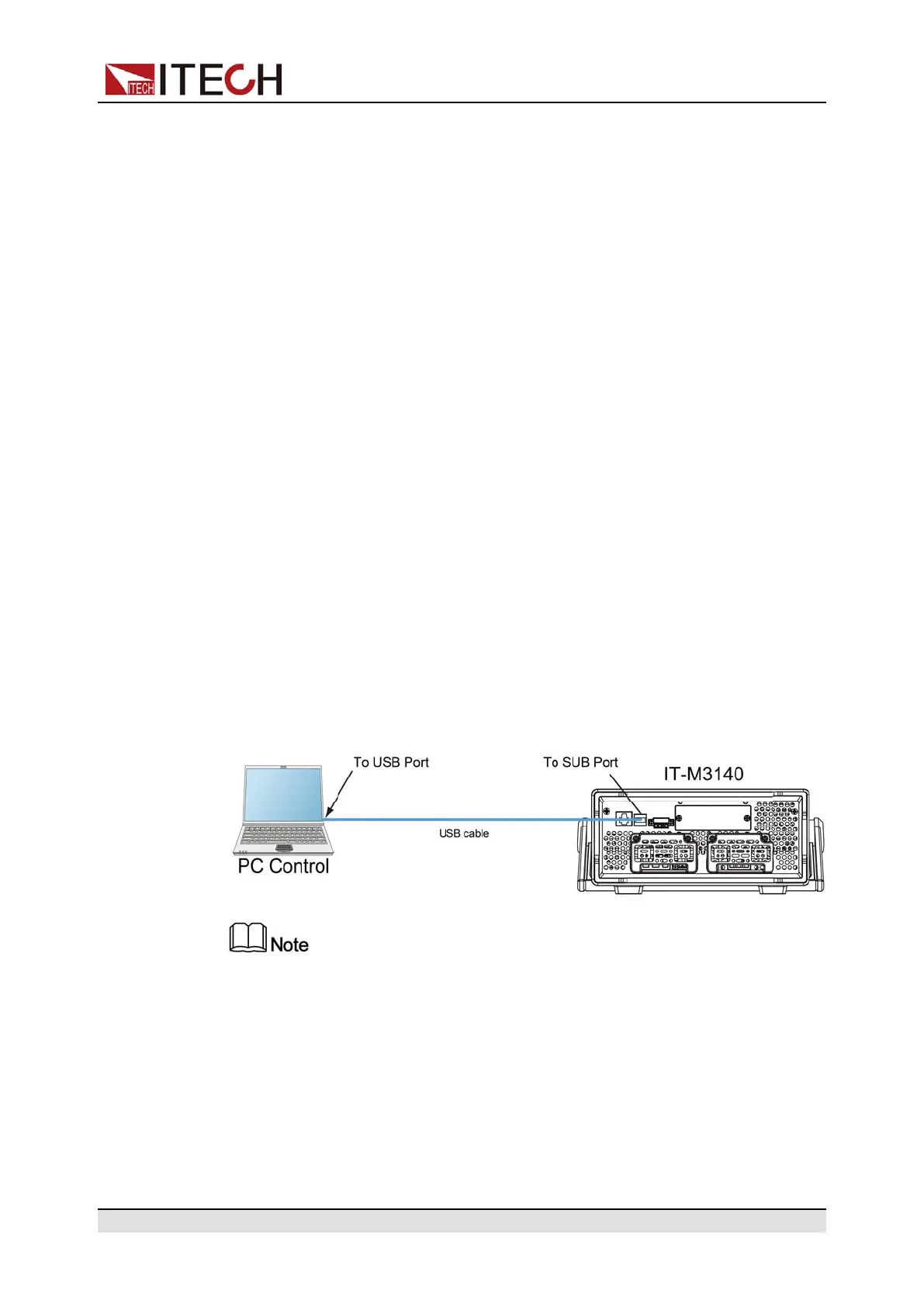
2.6.1 USB Interface
The USB interface is located on the rear panel of the instrument, the following
can help users quickly understand the steps required to connect the USB inter-
face. The figure below shows a typical USB interface system.
• The rear panel shown in the figure is only an example. The actual appearance of
the rear panel is subject to the specific instrument.
The operation steps to use the USB interface are as follows.
1. Refer to the USB connection diagram, Connect the power supply and the
computer using a cable with two USB interfaces (each end).
2. Select the USB interface type in the system menu.
a. Press [Shift]+[Save] (System) to enter into the system menu interface.
Copyright © Itech Electronic Co., Ltd.
24
 Loading...