Basic Operation
General Digital I/O Function
• Under the default condition (Not-Invert), when the pin (1 to 7) is configured
as Output, it can output the high level (False) or low level (True).
If the corresponding pin is configured as Invert, it means that the digital
signal is inverted and will output low level or high level.
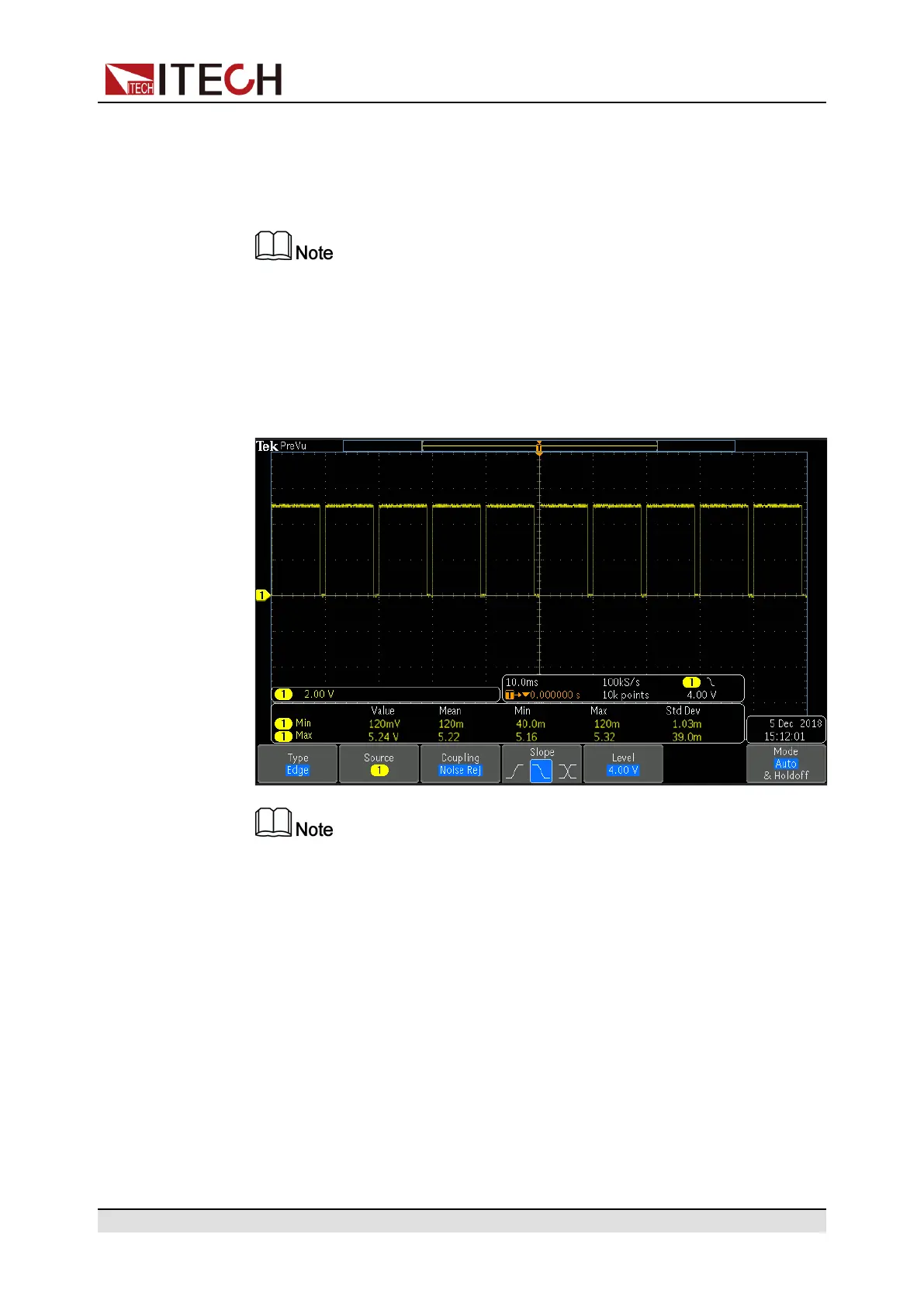
• Under the default condition (Not-Invert), when the pin (1 to 7) is configured
as Output→PWM, the user needs to set the frequency (PWM Freq) and du-
ty cycle (PWM Duty) values. For example, if the PWM Freq is set to 100Hz
and the PWM Duty is set to 10%, the output waveform is as follows:
In the above figure, the peak voltage (minimum value) is 5.16V and the
cycle is 10ms. The high level duration is 9ms and the low level duration is
1ms in one cycle.
• Under the default condition (Not-Invert), when the pin (1 to 7) is configured
as Input, it means the instrument can detect the level status of the external
input. By default (i.e., the pin is not connected), it can be detected as high
level, and the front panel will display input(1). If the pin is configured as
Invert, it can be detected as low level, and the front panel will display input
(0).
Copyright © Itech Electronic Co., Ltd.
97