Quick Reference
2. Interface for optional accessories IT-E166 and IT-E167 (For details, see 1.9
Options Introduction)
3. Digital I/O interface: P-IO
4. CAN communication interface
5. LAN communication interface
6. External control interface CTRL
7. USB communication interface
8. Communication interface of outer ring optical fiber (TX and RX)
9. DC output terminals of the power supply
10.AC power input terminals (L1, L2, L3, and PE)
11. Cabinet earthing rod
1.6 VFD Indicator Lamps Description
The IT6000C series Bi-directional Programmable DC Power Supply VFD indica-
tor lamps description is as follows:
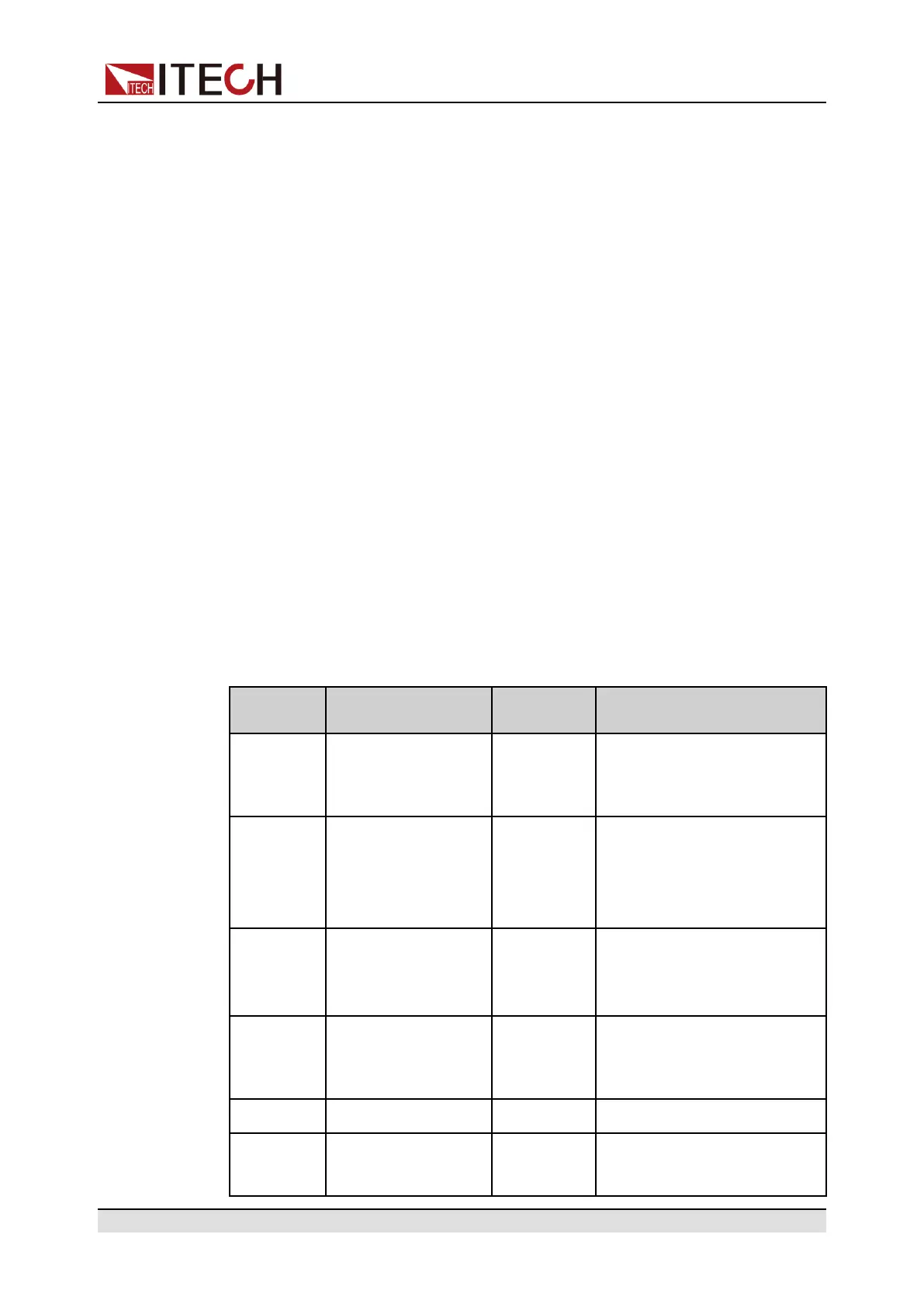
Table 1–1 VFD Indicator Lamps Description
Flag Function
Description
Flag Function Description
OFF The output of the
power supply is
turned off.
Sense Sense function of the power
supply is enabled.
CV The power supply is
in a state of con-
stant voltage
output.
Rear Analog function begin to
work.
CC The power supply is
in a state of con-
stant current output.
Addr When received command
successfully, the flag will dis-
play 3 seconds.
* The keyboard lock
is turned on.
Rmt Indicates that the instrument
is working in remote control
mode.
CR None Error Error occur
Shift Using composite
function key
Prot The instrument enters the
protection state.
Copyright © Itech Electronic Co., Ltd.
9