Inspection and Installation
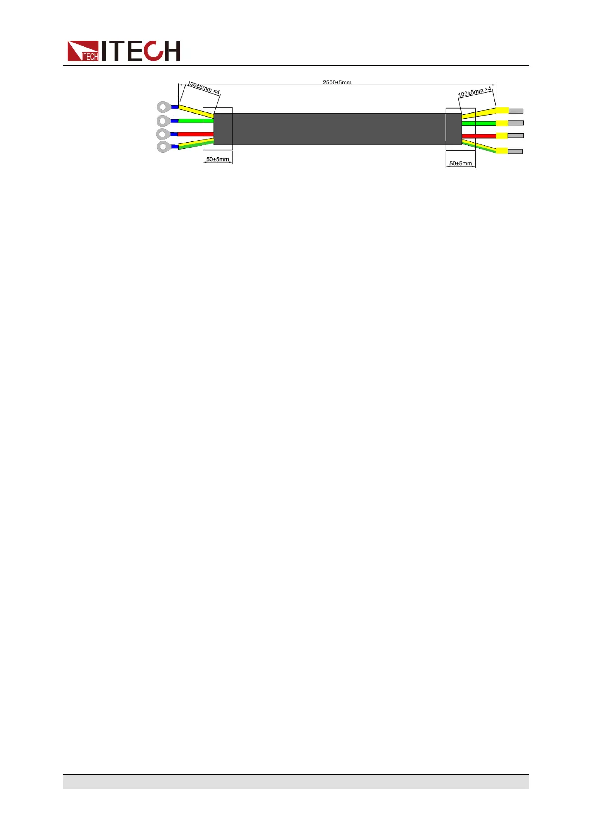
The red, green and yellow wires are live wires, which are correspondingly con-
nected to the L1, L2 and L3 terminals of power input on the rear panel of the in-
strument; the yellow-green wire is grounding wire, which is connected to the PE
terminal of power input on the rear panel.
AC Power Input Level
The input of this series is a three-phase AC power of 380V. (Line voltage: such
as the voltage between L1 and L2).
• Voltage: 380V±10% (Three-phase four-wire)
• Frequency: 47Hz to 63Hz
Connecting the Power Cord
• For 3U model, see the steps below to connect the power cable.
• For units already assembled into a cabinet during ex-factory, if one end of
the power cable is connected, the user needs to connect the other end of
the power cable to the distribution box. The connection method is same as
that for the 3U model;
• For models to be assembled in parallel by the user, see contents related to
power cable connection in Cabinet Assembly Instruction.
1. Confirm that the switch of the AC power distribution box is off.
2. Confirm that the power switch is in the OFF position and verify that there is
no dangerous voltage on the connection terminals.
3. Remove the protective cover outside the AC input terminal on the rear
panel.
4. Connect one end of the power cable’s round terminal to the AC power input
terminal on the instrument’s rear panel.
a. You only need to connect the red, green and yellow live wires to the ter-
minals on the rear panel, which are not required to correspond to L1, L2
and L3 terminals one by one.
b. The yellow-green wire is grounding wire, which is connected to the pro-
tective grounding terminal (PE).
Copyright © Itech Electronic Co., Ltd.
22
 Loading...

