Initializing, Programming, and Connecting the ERT Module
TDC-0951-005 100W-R and 100WP-R Datalogging ERT Module Installation Guide 10
Proprietary and Confidential
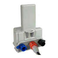
Connecting the 100WP-R to a Remote Meter Register
Connect the 100WP-R wires from the ERT module to the register screw terminals according to the following
table.
Register screw color designator
Itron (Actaris) Cyble Sensor (2-
wire)
Remaining wire must be connected to both
ERT module wires
Connect the ERT module to the cable using gel-cap connectors (see Using Gel Cap Connectors on page 37).
Verifying 100W-R and 100WP-R ERT Module Operation
Use one of the following handheld computers to verify the ERT module is correctly recording consumption
data.
FC200SR
FC300 with SRead
Caution
Each handheld radio requires special setup and configuration parameters to
successfully read and program 100W modules. Refer to the respective meter
reading application for specific instructions.
Do not use ReadOne Pro, FS2PN and FS3PN, or FC200R handhelds to read the
100WP-R. These readers do not operate their receivers long enough or at the right
frequency to reliably capture a 100WP-R transmission.
Refer to the user guide for your programming device (see Related Documents on page 2) and data collection
application for more information.