Installing the 100W-R and 100WP-R ERT Modules
TDC-0951-005 100W-R and 100WP-R Datalogging ERT Module Installation Guide 22
Proprietary and Confidential
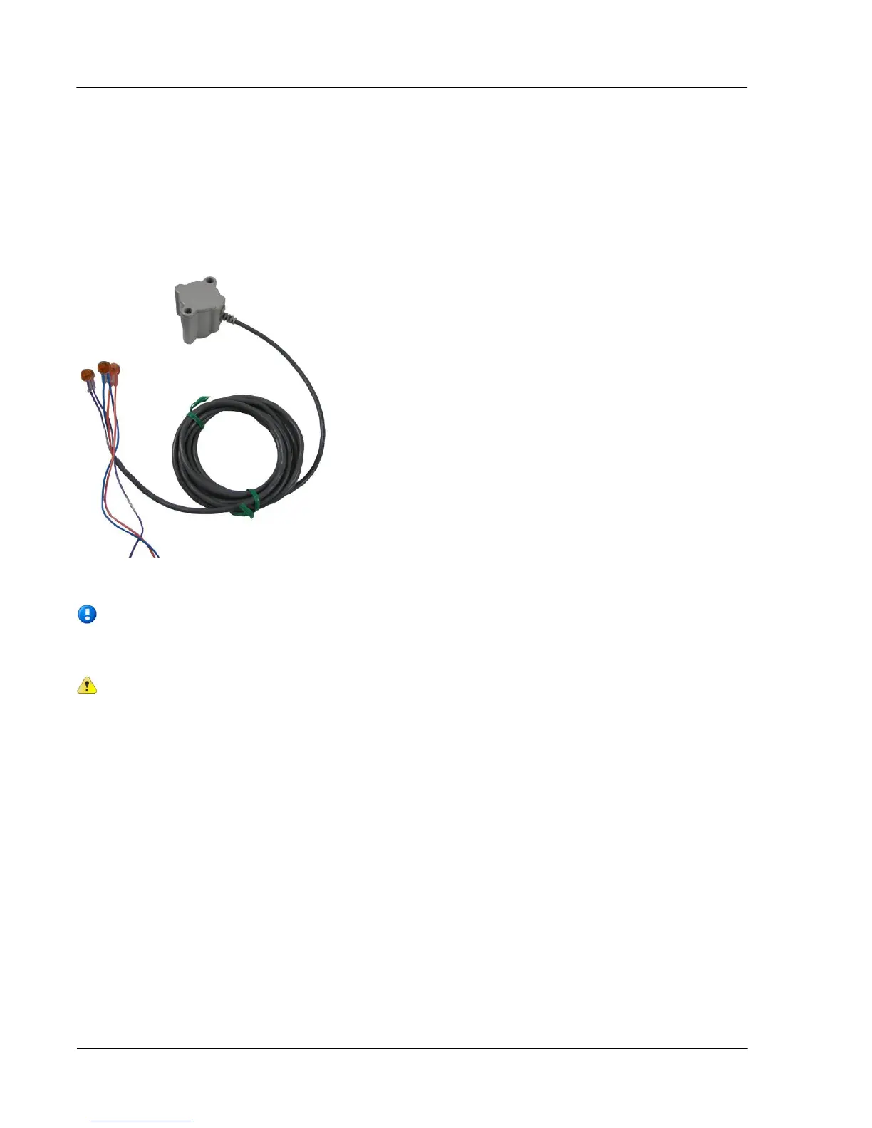
Connecting the Leak Sensor to the 100W-R and 100WP-R ERT Modules
Connecting a Leak Sensor to the 100W-R and 100WP-R ERT modules requires a Leak Sensor enabled ERT
module. See 100W-R and 100WP-R Models on page 4. Connect the ERT modules flying lead wires to the
Leak Sensor (using gel cap connectors, see Using Gel Cap Connectors on page 37) matching wire colors to
complete the three connections.
See Optional Leak Sensor Installation on page 21 for Leak Sensor mounting information.
Note If the ERT module will mount on the exterior of the house but the Leak Sensor is on a
pipe on the interior, the Leak Sensor cable must run through a hole in the wall before connecting
it to the ERT module.
Caution Extension cable lengths must not exceed 300 ft. Extension cabling from Itron is
stranded, tinned, and pre-bonded for reliability and proper connection to gel cap connectors.
Extension cabling manufactured by non-approved Itron manufacturers may result in unreliable
and problematic connections. Contact Itron Support for more information.

 Loading...