Installing the 100W-R and 100WP-R ERT Modules
TDC-0951-005 100W-R and 100WP-R Datalogging ERT Module Installation Guide 27
Proprietary and Confidential
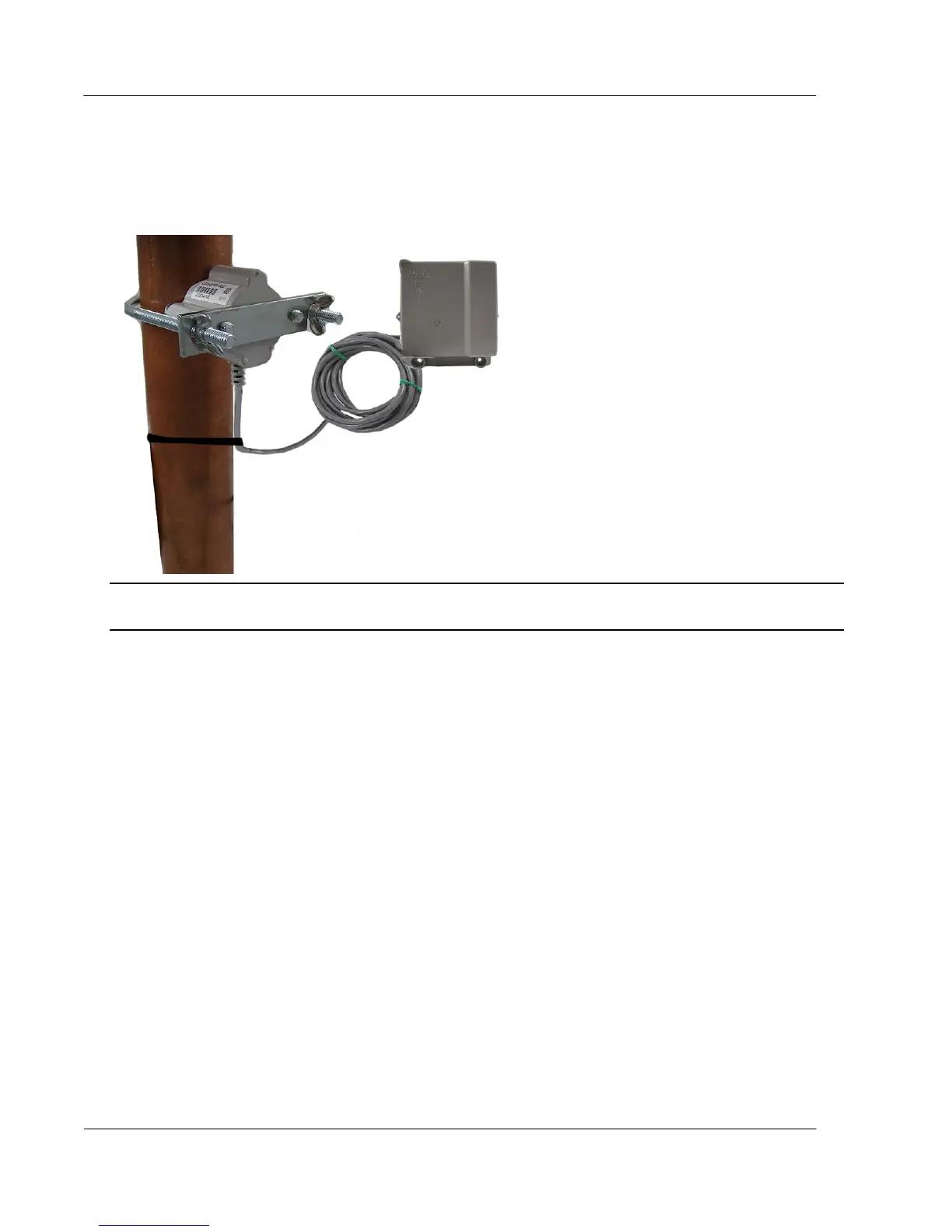
5. Insert the U-bolt around the pipe and into the holes in the plate/Leak Sensor assembly. Secure the U-bolt
with the wing nuts. Tighten the wing nuts until snug (to a minimum of 5-inch pounds) to prevent device
rotation on the pipe. After the second wing nut is tightened, check the Leak Sensor to verify the device is
snug. If the sensor moves, tighten the wing nuts until there is no movement.
Caution Do not tighten the Leak Sensor to more than 20 inch-pounds. Over-tightening could damage the
Leak Sensor housing and/or the pipe.
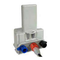
Remote Mount Installation
Connect the ERT module to the register as described in Connecting, Initializing, and Programming the ERT
Module on page 7.
Using a back plate, create a template by drilling through a back plate lug slot to mark the position of the
screw. Use the drilled back plate as your mounting template.
The arrow on the ERT module must point up when installation is complete.
Required Tools and Hardware
Remote mount installation requires the following tools and hardware:
Remote Mount Kit (CFG-0771-021 or CFG-1300-003) includes the back plate, tamper seals, and
mounting screws
Nut driver or similar tool
Phillips screwdriver
Drill and bits for mounting surface and screw size