Installing the 100W-R and 100WP-R ERT Modules
TDC-0951-005 100W-R and 100WP-R Datalogging ERT Module Installation Guide 29
Proprietary and Confidential
6. Insert a tamper seal over each mounting screw and drive into place with a nut driver or a similar tool.
Note A tamper seal is fully seated when the top of the tamper seal is approximately 1/16 inch below the
top of the screw recess.
7. Secure any excess cable using the provided cable ties.
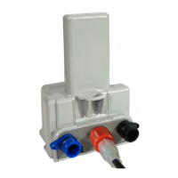
Direct-Mounting to the Meter Register
Direct mounting ERT modules to a meter register requires a register designed for that purpose. This section
describes 100W-R and 100WP-R installation for the following direct mount registers:
Badger ADE and RTR
Elster/AMCO (ABB) Scancoder, InVISION, and Digital
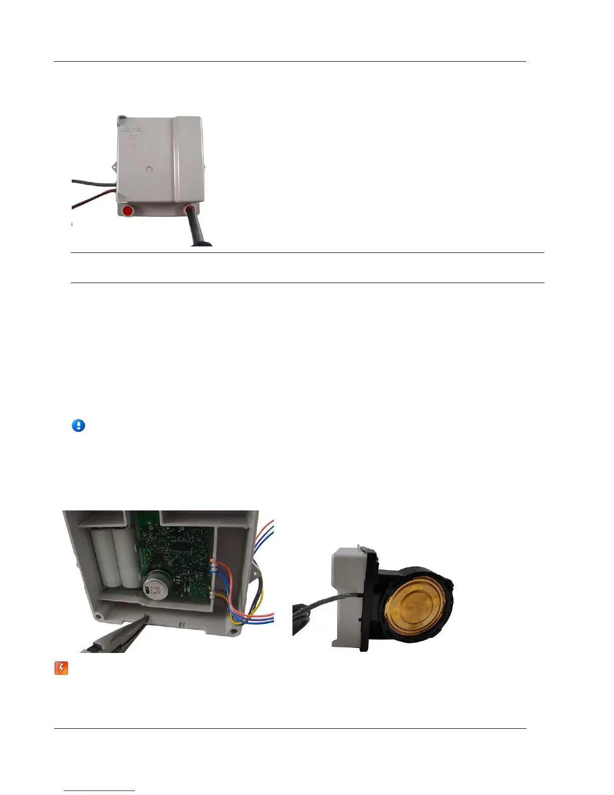
Note If you are installing an ERT module with Leak Sensor capability, use a needle-nose pliers to
remove one of the ERT module's housing knock-outs to accommodate the Leak Sensor cable. If
your meter register has a raised internal rim, remove the larger case knock-out. When you are
installing a Leak Sensor with the 100W-R or 100WP-R, you must install cable strain relief prior to
installing the ERT module. For more information, see Installing 100W-R and 100WP-R Cable
Strain Relief on page 11.
Warning Do not use the direct mounting method in a pit environment. Use a pit ERT module for pit
environments. 100W-R and 100WP-R ERT modules direct mounted in a pit environment are not
covered by the Itron warranty.