Installing 40W and 50W ERT Modules
SECTION 2. INSTALLING THE BADGER DIRECT-MOUNT
01547
NOTE
The register may or may not be mounted on the meter when performing the following steps.
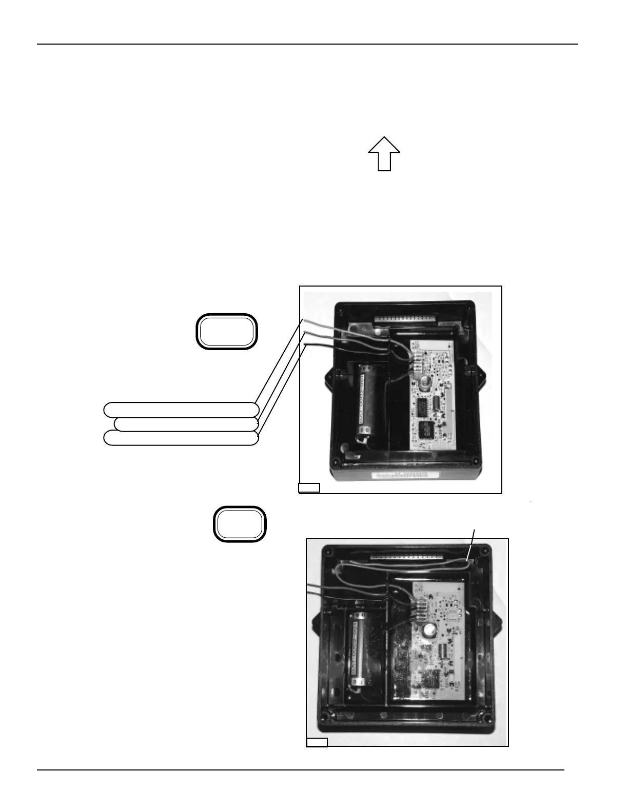
Obtain an ERT module for the Badger
register. ERT modules have three
wires:
one wire with green insulation
one wire with red insulation
one wire with black insulation
2-1
Check the part number on the label to make sure the ERT module matches the meter (reference Table
1-1).
Always install an ERT module right side up, as indicated by the on the label.
Make sure you have a Badger register with a direct-mount bracket (as shown in Section 1).
CAUTION: If an ERT module is dropped from a height of 3 feet or more, there may be damage to the circuit
board. DO NOT install the ERT module.
01547a
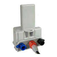
Connect the black wire from the register to the
black wire from the ERT module with a gel connec-
tor, as described in Appendix A of this manual. Do
the same with the red wire. The green wire is not
used.
2-2
NOTE: Fold the unused green wire
down into the ERT module housing.
UP
2-1