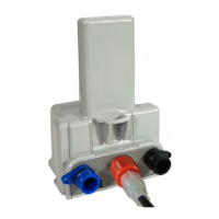
Installing 40W and 50W ERT Modules
SECTION 6. INSTALLING A REMOTE MOUNT
Check the part number on the label to make sure the ERT module matches the meter (reference Table
1-1).
Always install an ERT module right side up, as indicated by the on the label.
CAUTION: If an ERT module is dropped from a height of 3 feet or more, there might be damage to the
circuit board. Do not install the ERT module.
NOTE: All 40W & 50W ERT modules can be remote mounted above grade outside.
Get a supply of 19-26 gauge, pre-bonded or solid conductor wire with a maximum diameter of .082" (individual
wire with insulation). Note the Badger RTR register and the ADE register come with 3 feet to 100 feet of cable
(typically 25 feet). All other cable is to be supplied by the customer. Total cable length should not exceed
300 feet (500 feet for Badger).
INSTALLATION TIP: Some installers prefer to first run the wire from the water meter to the point where the
ERT will be installed and then connect the wire to the register, and lastly connect the other end of the wire to
the ERT. Any order is acceptable, and this is simply installer preference. If you use existing wire, do a
continuity check first.
NOTE: If customer-supplied wire is not color coded red, green, and black, care must be taken that each of
the 3 individually colored wires is installed correctly. For example, if customer supplied wire is pink, gray and
yellow, and the installer connects at the register the pink wire to the register's red (R), the gray wire to the
register's black (B), and the yellow wire to the register's green (G), then the installer must connect the other
end of those wires to the ERT as follows:
• Pink wire to ERT red wire
• Gray wire to ERT black wire
• Yellow wire to ERT green wire.
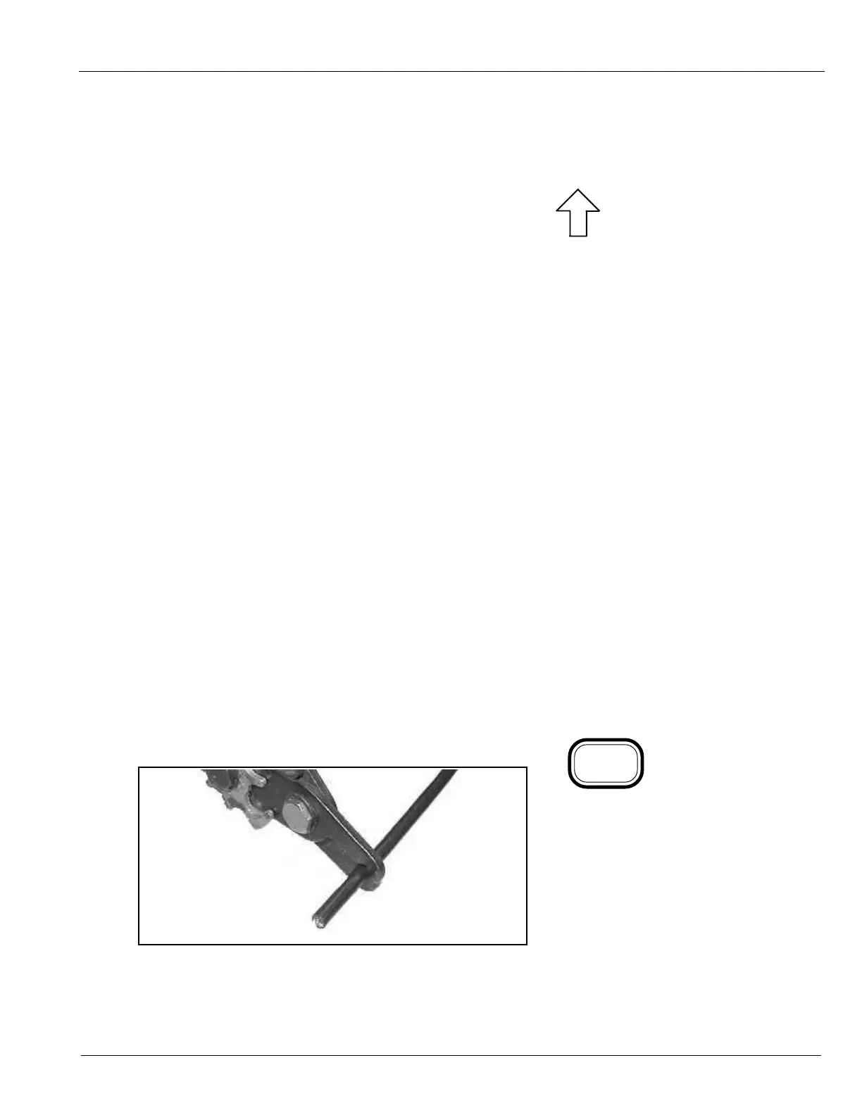
Using a wire stripper, remove about
3" of the outer insulation from the
wire.
Strip 1/2-inch of insulation from each
of the three color coded wires.
6-1
UP
NOTE
The register may or may not be mounted on the meter
when performing the following steps.
Obtain adequate supply of wire (in-
staller supplied).
6-1