Installing 40W and 50W ERT Modules PUB-0126-001 4/04
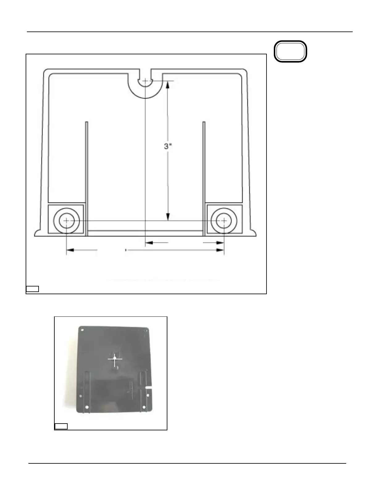
Drill three pilot holes in the
mounting surface the proper
size for the mounting
screws, as shown.
CAUTION
Make sure that you do not
damage anything on the
other side of the surface
you are going to mount
the remote mounting
bracket on when you drill
the holes and install the
screws.
IMPORTANT
The holes for the bottom
two screws must be on a
horizontal line.
NOTE
If you do not use the mount-
ing screws furnished with the
ERT module, be sure to use
screws that have the same
size head as those furnished
with the ERT module.
6-19
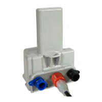
INSTALLATION TIP
If you have several installations, you can make a durable
template as follows:
Drill a hole through the lug slot of a mounting bracket,
where indicated, to mark the position of that screw. Keep
this permanent template for future use.
00222F
6-9
DRILLING TEMPLATE--ACTUAL SIZE
3-3/8"
1-21/32"
00498