Installation
8 PanCam/Pantel/Pancode
Installation and Programming Manual
2.1.3
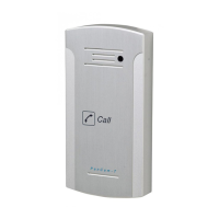
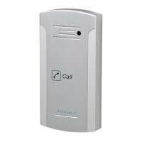
Pantel/Pancode
The Pantel/Pancode can be installed as the individual access
co
ntrol or can be used with adjacent access
-
control devices,
such as card reading devices. For more information on
adjacent access
-
control device installation, see section 2.2,
Adjacent Access
-
Control Device
.
A 12V AC external power supply is included with
the
Pantel/Pancode unit. A 12 to 24V DC/1.6A power adapter,
which provides a quieter door
-
lock action, can also power the
Pantel/Pancode. The power adapter should not be located
farther than 10m (30ft) from the Pantel/Pancode.
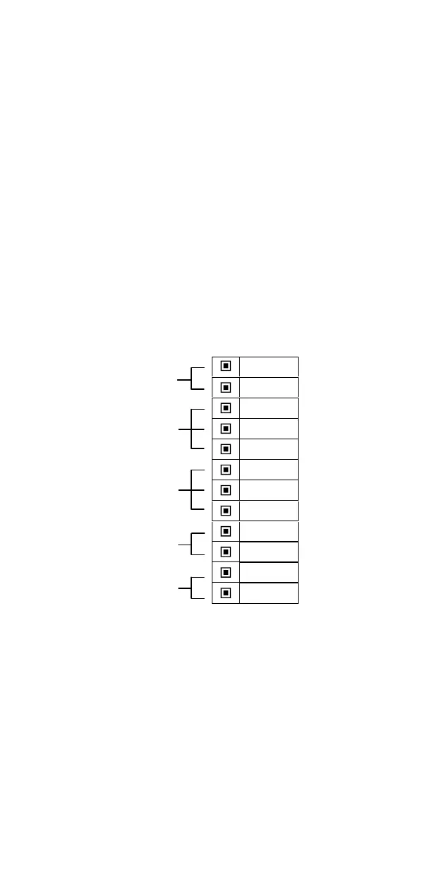
The following figure shows th
e terminal locations on the wire
connector provided with the Pantel/Pancode. This connector is
attached at the base of the internal component. All wiring to
the Pantel/Pancode is attached to the wire connector.
The Pantel/Pancode supports bypass switch in
stallation. This
allows opening the door with a hardwired switch. A bypass
switch should be connect to the SW and /SW terminals.
~12V
~12V
N.C.
CMN
N.O.
DLR
~DLR
/DLR
SW
/SW
LINE
LINE
Figure 2
-
4. Connector Wiring
Note
:
For installations of powered
-
unlocked
-state, use DLR
and ~DLR. For installations of powered
-
locked
-
state,
use /DLR and ~DLR (
this is recommended for safety
purposes in an emergency
situation
).
The wiring connector is a screw connector type. In order to
attach a wire you must insert the stripped end of the wire into
Power Supply
Normally
Open/Closed
Outputs
Door Lock
Relay
Termin
als
Switch
Terminals
Phone
Line/Extension