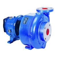
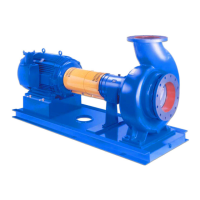
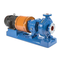
The Goulds Pumps Model 3196 i-FRAME is a horizontal overhung, open impeller, centrifugal pump designed to be ANSI B73.1 compliant. It is available with 5 power ends and 29 hydraulic sizes, making it adaptable to various applications. The pump's design emphasizes reliability, ease of installation, operation, and maintenance.
Function Description:
The primary function of the Model 3196 i-FRAME pump is to transfer liquids through a system. Its open impeller design is suitable for handling fluids with some solids, preventing clogging and ensuring efficient operation. The pump is designed for continuous duty in industrial applications, with robust construction to withstand demanding environments. It can be configured with various shaft-sealing options, including cartridge mechanical seals, conventional inside-component mechanical seals, conventional outside-component mechanical seals, dynamic seals, and packed stuffing boxes, to suit different fluid types and operational requirements.
Important Technical Specifications:
General:
- Pump Type: Horizontal overhung, open impeller, centrifugal pump.
- Compliance: ANSI B73.1.
- Power Ends: 5 different sizes (STi, MTi, LTi, XLT-i, i-17).
- Hydraulic Sizes: 29 different sizes.
- Casing: Top-centerline discharge, self-venting, integral foot support for maximum resistance to misalignment due to piping loads.
- Standard Flange: ANSI flat-faced serrated flange.
- Optional Flanges: ANSI class 150 raised-face serrated flange, ANSI class 300 flat-face serrated flange, ANSI class 300 raised-face serrated flange.
- Impeller: Fully open, screwed onto the shaft, sealed from pumped liquid by a Teflon O-ring (for 3196 models).
Power End (Bearing Frame):
- Frame Adapter: Ductile iron, machined rabbet fitted to the seal chamber/stuffing box cover, precision dowel pin fitted to the bearing frame.
- Lubrication: Standard flood-oil lubrication (regreasable bearings and oil-mist lubrication are optional). Oil level checked via sight glass. No machining required for lubrication conversion.
- Seals: Labyrinth seals are standard for the power end.
- Shaft: Available with or without a sleeve.
- Bearings:
- Inboard Bearing: Single-row deep-groove ball bearing, carries only radial loads, free to float axially in the frame.
- Outboard Bearing: Shouldered and locked to the shaft and housing to carry radial and thrust loads. Double-row angular-contact bearing (except LTi, which uses a pair of single-row angular-contact ball bearings mounted back-to-back).
i-ALERT™ Condition Monitor:
- Function: Compact, battery-operated device for continuous vibration and temperature monitoring of the pump power end.
- Alerts: Blinking red LEDs for exceeding pre-set vibration and temperature limits. Single green LED for operational status and sufficient battery life.
- Alarm Mode Indication: Two red flashing LEDs within two-second intervals when limits are exceeded for two consecutive readings within a ten-minute period.
- Temperature Limit: 195°F (91°C).
- Vibration Limit: 100% increase over baseline level.
- Battery Life: Non-replaceable battery. Three to five years under normal operating conditions, one year in alarm mode.
- Activation: Activated by placing a small magnet over the ITT logo. Establishes baseline vibration level by averaging eight samples.
- Deactivation: Touch and hold a magnet over the ITT logo until red LEDs blink three times (10-15 seconds in normal mode, 5 seconds in alarm mode). Solid red LEDs indicate deactivation.
- Reset: Touch a magnet over the ITT logo to establish a new baseline after maintenance or system changes.
Usage Features:
- Installation Flexibility: Can be installed using shims/wedges, jackscrews, spring mounting, or stilt mounting, accommodating various foundation types and piping configurations.
- Alignment: Detailed procedures for pump-to-driver alignment (angular and parallel, vertical and horizontal corrections) using dial indicators, with specified cold and hot alignment tolerances. C-face adapters simplify alignment by automatically aligning shaft within specified limits.
- Priming: Instructions for priming with suction supply above or below the pump, including opening air vents and using foot valves/outside liquid sources.
- Startup: Precautions for startup, including verifying driver settings, warm-up rates, and flushing procedures. Emphasizes monitoring pressure, vibration, bearing temperature, and noise during operation.
- Shutdown: Procedures for safely shutting down the pump, including closing discharge valves and locking out the driver.
- Hazardous Fluids: Designed for use with hazardous liquids, with clear warnings and procedures for safe handling, decontamination, and personal protective equipment.
- Ex-approved Products: Special handling and installation requirements for Ex-approved units in potentially explosive atmospheres, including personnel certification, product usage restrictions, and compliance with international standards (IEC/EN 60079-17, ATEX Directive 94/9/EC, FM according to NEC).
Maintenance Features:
- Maintenance Schedule: Includes routine, three-month, and annual inspections. Intervals are shortened for abrasive/corrosive fluids or explosive environments.
- Bearing Lubrication: Detailed requirements for oil-lubricated and grease-lubricated bearings, including oil volumes, acceptable lubricant brands, and temperature-based oil/grease recommendations. Procedures for regreasing and post-shutdown lubrication.
- Shaft Seal Maintenance: Instructions for mechanical seals (cartridge, conventional inside/outside component) and packed stuffing boxes, including flushing methods, leakage rate adjustments, and replacement guidelines. Dynamic seals require minimal maintenance unless abrasive/corrosive.
- Disassembly/Reassembly: Comprehensive instructions for disassembling and reassembling pump components, including coupling, back pull-out assembly, impeller, seal chamber cover, stuffing box cover, dynamic seal, frame adapter, and bearing frame. Emphasizes safety precautions, required tools, and inspection criteria for parts.
- Part Inspection: Guidelines for inspecting casing, impeller, frame adapter, seal chamber, stuffing box cover, shaft, sleeve, bearings, and bearing housing for wear, cracks, pitting, and corrosion. Includes tables for shaft runout tolerances and bearing fits.
- Lubrication Conversion: Procedures for converting frame lubrication from greased-for-life/regreasable to oil-lubricated bearings, and from flood-oil to pure-oil mist or regreasable.
- Troubleshooting: Extensive troubleshooting guides for operational issues (e.g., pump not delivering liquid, noisy operation, hot bearings), alignment problems, and assembly issues.
- i-ALERT™ Condition Monitor Maintenance: Guidelines for disposal of the condition monitor, emphasizing battery safety and adherence to local laws.
- Spare Parts: Provides a detailed parts list with material specifications and quantities, emphasizing the importance of using genuine ITT parts for service reliability.