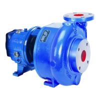
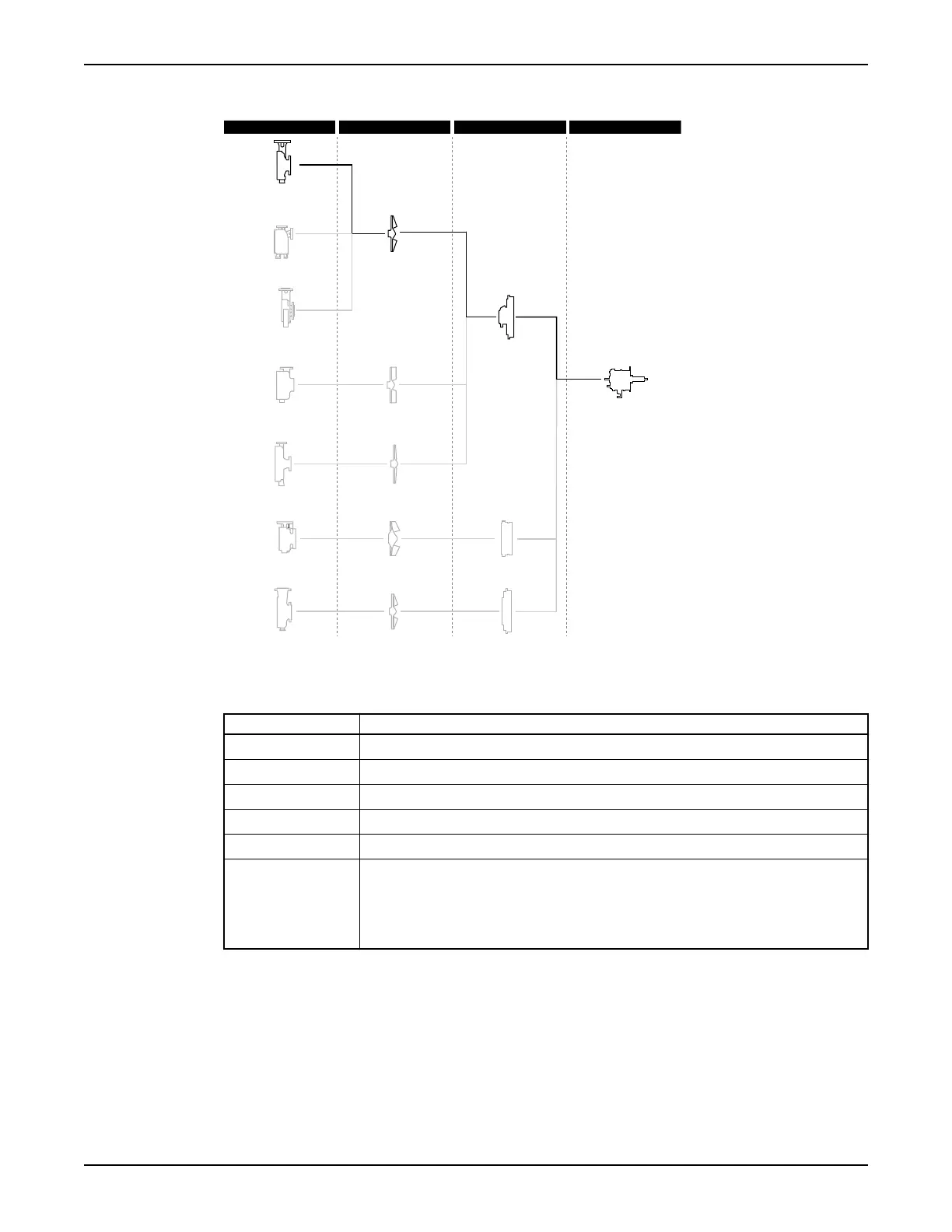
Part description 3196
3196
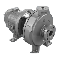
3796
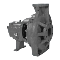
HT 3196
CV 3196
LF 3196
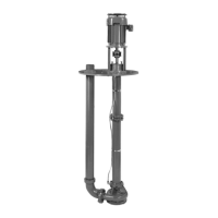
3198
NM 3196
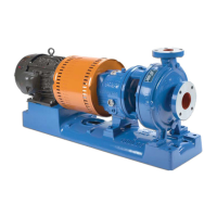
Casing Impeller Cover Power end
Figure 6: 3196 part description
This table describes the pump casing parts.
Table 3: Casing
Part Description
Discharge Top-centerline
Casing ventilation Self venting
Gasket Fully confined
Mounting method Integral foot support for maximum resistance to misalignment due to piping loads.
Standard flange ANSI flat-faced serrated flange
Optional flanges One of the following flanges can be used:
• ANSI class 150 raised-face serrated flange
• ANSI class 300 flat-face serrated flange
• ANSI class 300 raised-face serrated flange
Impeller
The impeller is
• fully open
• screwed onto the shaft
The threads are sealed from the pumped liquid by a Teflon O-ring for the 3196.
Product Description
14 Model 3196 i-FRAME Installation, Operation, and Maintenance Manual