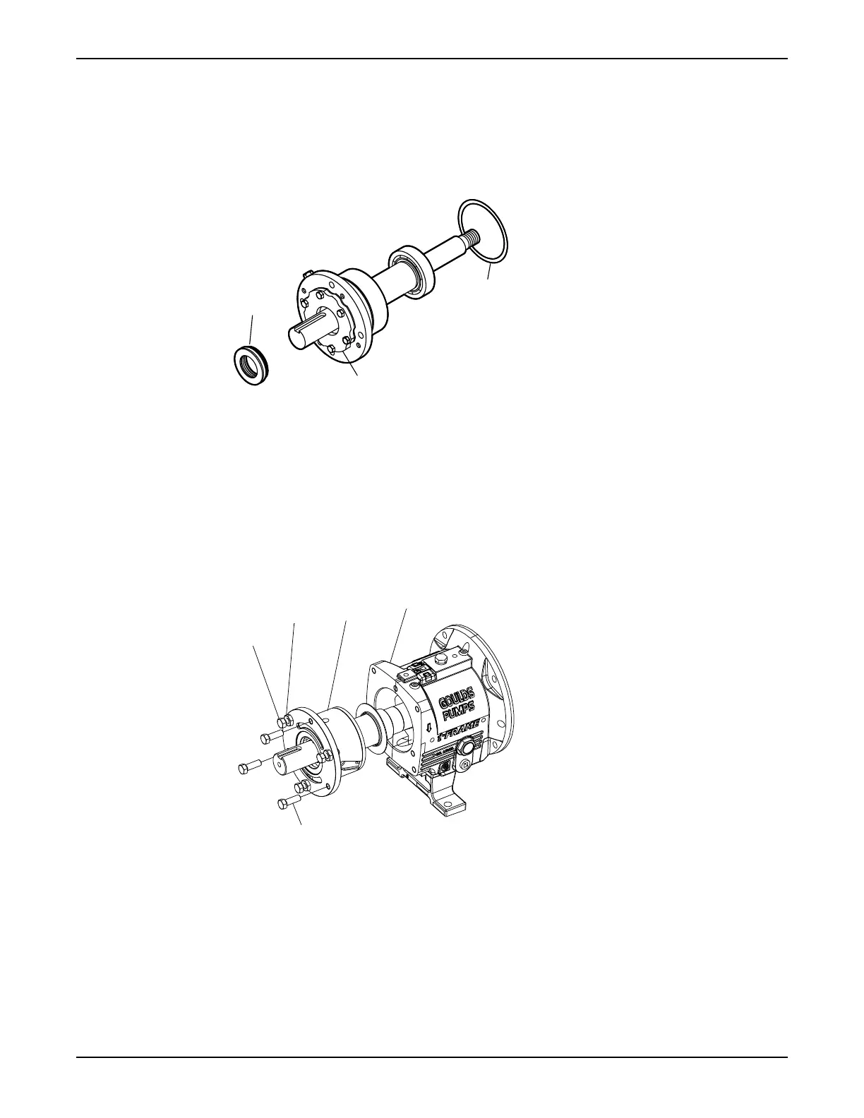
9. Install the remaining parts onto the bearing shaft as follows (see the illustration):
a) Install a new O-ring (496).
b) Install the outboard labyrinth oil-seal (332A) into the end cover (109A).
Place the drain slots of the oil seal at the bottom position (6 o’clock).
Make sure that the edges of the keyway are free from burrs. To protect the O-ring, cover the
keyway lengthwise with a piece of electrical tape before you install the oil seal.
10. Install the shaft assembly into the bearing frame as follows (see the illustration):
a) Coat the outside of the bearing housing (134) with oil.
b) Coat all the internal surfaces of the bearing frame (228) with oil.
c) Install the shaft assembly into the bearing frame (228).
Make sure that the shaft rotates freely.
d) Install the clamp bolts (370C) in the bearing housing (134) and tighten by hand.
e) Install the jack bolts (370D) with the locknuts (423) in the bearing housing (134) and tighten by
hand.
f) Attach the bearing-frame foot (241) and fasten the bolts (370F) by hand.
Assemble the frame
1. Support the frame assembly in a horizontal position.
2. Check the shaft-end play by moving the shaft forward and backward by hand, and note any indicator
movement.
Maintenance
108 Model 3196 i-FRAME Installation, Operation, and Maintenance Manual