4. Thread the locknut (136) onto the shaft (122) and tighten it until it is snug.
5. Bend the tangs of the lockwasher into the slots of the locknut.
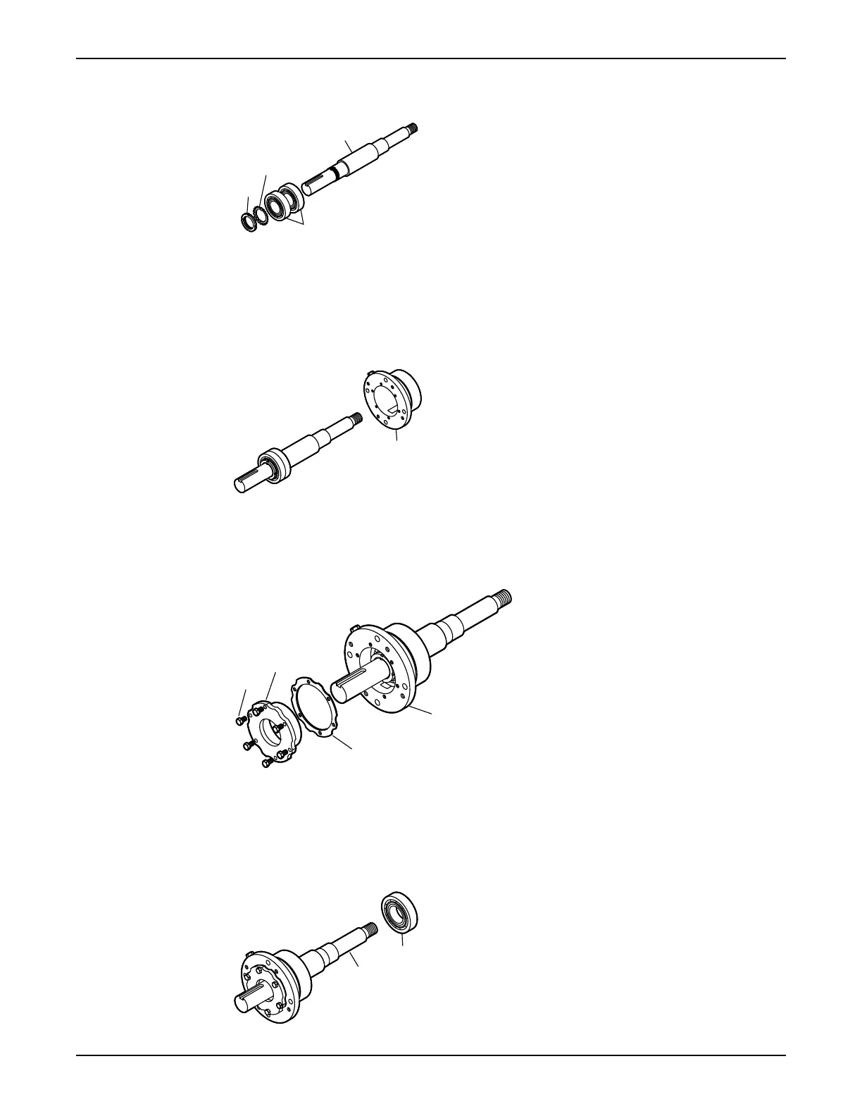
6. Install the bearing housing as follows (see the illustration):
a) Coat the outside of the outboard bearing (112A) with oil.
b) Coat the bore of the bearing housing (134) with oil.
c) Put the bearing housing (134) onto the shaft.
Do not use force.
7. Fasten the gasket (360C) and the end cover (109A) with the bolts (371C).
See the specified torque values.
Make sure that the shaft rotates freely.
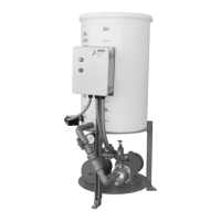
8. Install the inboard bearing as follows (see the illustration):
a) Coat the inner surfaces of the bearings with lubricant.
b) Put the inboard bearing (168) onto the shaft (122).
The regreasable bearing has a single shield. Make sure that the bearing is installed with the shield
away from the impeller.
Maintenance
Model 3196 i-FRAME Installation, Operation, and Maintenance Manual 107
 Loading...