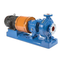
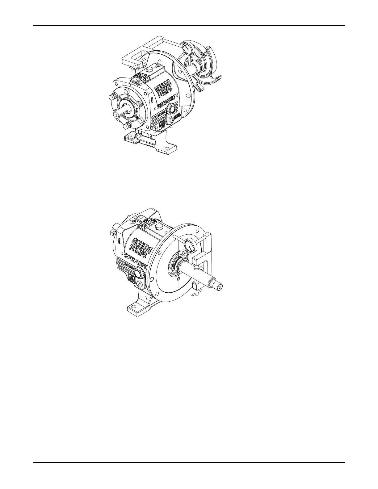
4. Check the frame-face runout by rotating the shaft so that the indicator measures the fit for 360º.
If the total indicator reading is greater than 0.001 in. (0.025 mm), then disassemble and determine the
cause.
5. Place the manila gasket (360D) on the frame (228), and hold the gasket in place by inserting the dowel
pins (469B) in their holes.
The gasket is designed to fit only one way.
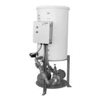
6. Install the frame adapter.
a) Place the frame adapter (108) onto the frame assembly.
b) Align the bolt holes and dowel locations on the frame adapter with the bolt holes and dowel
locations on the frame.
Maintenance
110 Model 3196 i-FRAME Installation, Operation, and Maintenance Manual
 Loading...