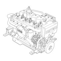
- Using the w rench 99368503 (4), loos en t he check nut
(1) of t he adjuster sc rew (2).
- Insert the tappet feeler gauge (0,50 mm) 99368545 (3).
- With wrench, screw or unscrew the adjuster screw (2).
- Check that the tappet feeler gauge (3) can slide with a
slight amount of friction.
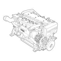
- Keeping the adjuster screw still (2), use wrench
99368503 (4) to lock the check nut (1) of the adjuster
screw.
Figure 60
Figure 61
Figure 62
Figure 63
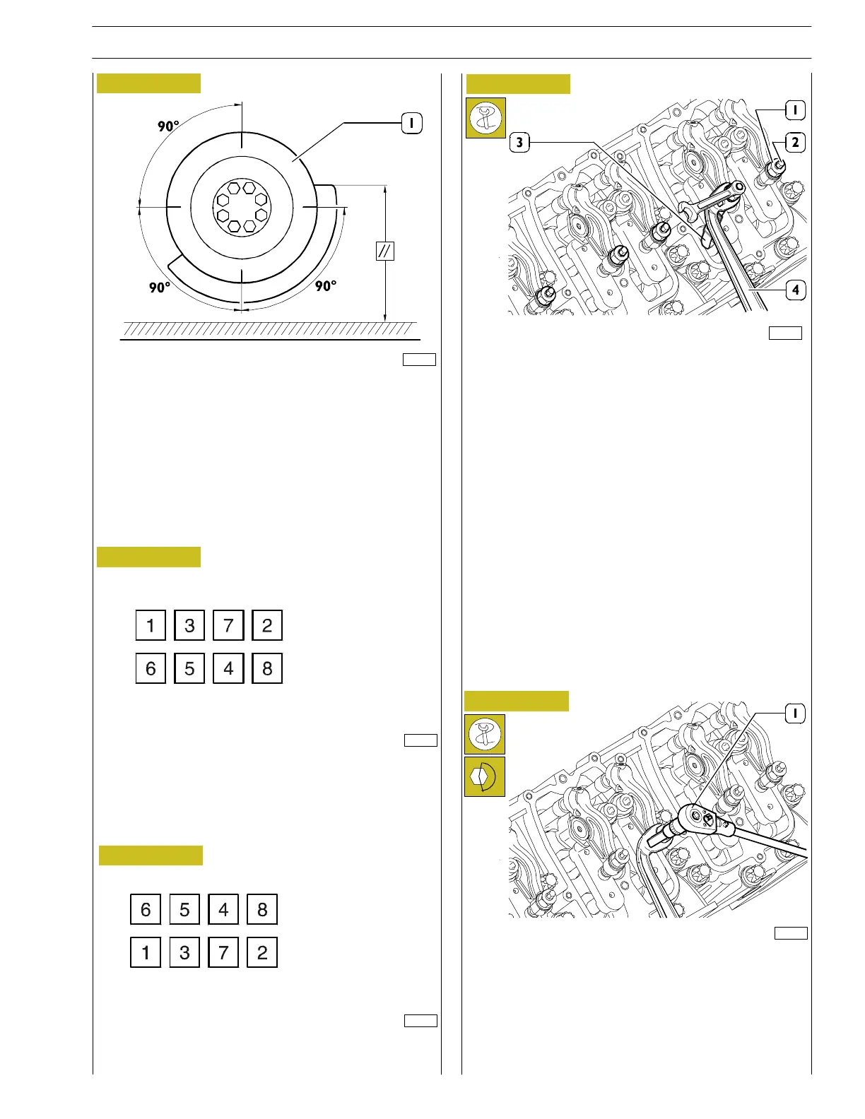
- To obtain cylinder no.1 or no.6 in T.D.C. con ditions it is
necessary to position the damping flywheel as indicated
in the picture. For th e following balancin g/adjustments it
is recommended to trace some marks on t he flywheel
(1), placed at 90° one from t he other (see picture).
- After obtaining this condition of balancing we move on
to adjust the valves in the following order:
- To make the adjustment, proceed as illustrated here:
BALANCING
ADJUST
FIRST STEP
BALANCING
ADJUST
SECOND STEP
- Apply the 10 — 60 Nm torque wrench with the 3/8”
square c onnection 99389831 (1) to the wrench
99368503 to lock the nut (1, Figure 63) to a torque of
34 to 44 Nm.
- Adjust the clearance between all valves and all rockers.
- Extract the tool for turning the flywheel and close the
flywheel cover.
Figure 64
83505
82722
81605
82723
81606
SECTION 3 - INDUSTRIAL APPLICATION
29
VECTOR 8 ENGINES
Print P2D32V001E Base - April 2006