Figure 89
Figure 90
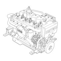
- Fit the new case (2) in the cylinder head (1) and
cold—head its bottom seat, on the cylinder head, with the
cold—heading tool 99365063 (3).
Figure 91
Figure 92
- Restore the hole in the case (2) with the reamer
99394017 (3) and the bushing 99394019 (1).
Restore the injector recessing, in relation to the face of the
cylinder head, with the milling cutter 99394018 (4) and
bushing 99394019 (1) that must be from 0.47 to 1.16
mm.
Figure 93
Figure 94
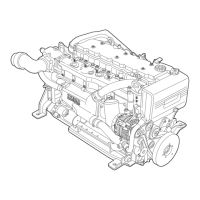
PRINCIPAL DATA FOR CHECKING SPRINGS FOR
INTAKE AND EXHAUST VALVE
kg 45± 2,5
kg 80±4
- Before mounting, check the flexibility of the valve spring
using tool 99305047. Compare the loading and
deformation data with those of the new spring indicated
in the following diagrams.
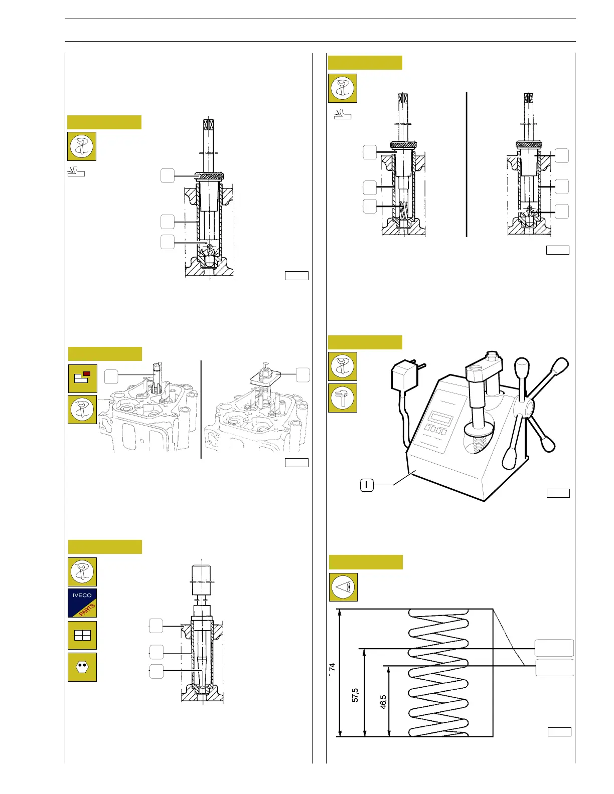
REPLACING THE INJECTOR—HOLDER
CASES
Imperfect coupling between the injector and case, forced into
the cylinder head or between the c ase and the seat on the
cylinder head, causes a loss of compression or water leakage.
In the first case, the trouble is eliminated by regrinding the seat
of the case (2) with the milling cutter 99394011 (3) and the
bushing 99394019 (1) taking account that the electro—injector
recessing from the cylinder h ead face must be from 0.47 to
1.16 mm.
In the second case, it is necessary to replace the case as follows:
- thread the case with the set of screw taps 99390800 (1);
- extract the case from the cylinder head with tool
99342145 (2).
1
2
3
1
2
1
2
3
1
2
1
2
3
4
16690
37722
82718
16859
2280
SECTION 4 - OVERHAUL AND TECHNICAL SPECIFICATIONS 37
VECTOR 8 ENGINES
Print P2D32V001E Base - April 2006