3 ADJUSTMENTS
16
3.17 REMOVING THE CUTTING UNIT _____________________________________________
1. To prevent contamination of the hydraulic system, as
well as loss of oil, do not disconnect the hoses from
the motor.
2. Raise and lo ck th e l ift a rms in tr ansport mode
(Section 3.4) and di sconnect the down pr essure
springs.
3. Remove transport pin then lower the lift arms to the
ground.
4. Remove hardware se curing moto r to dr ive housing
and carefully pull the motor away.
5. Place mo tor in a clean plastic b ag an d co ver th e
opening in the gear box.
6. Remove pin and collar fr om c enter ( rear) li ft ar m
and pul l the center cu tting uni t away fr om th e
mower.
7. Remove the hardware securing the front lift arms to
the c utting units, an d s lide th e m owers ou t o f th e
way.
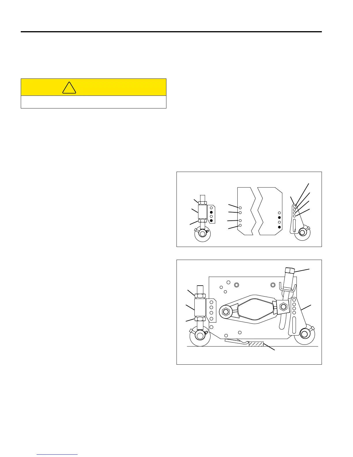
3.18 CUTTING HEIGHT - FIXED MODE ____________________________________________
Follow the procedures outlined in Section 3.16.
1. Reposition the rear roller adjuster.
a. For c utting heights from 3/8 to 1- 3/4 i n. (9 t o
44 mm), use holes (M) on the mower frame, and
two holes (shown in black) of the height adjuster
(F) as shown.
b. For c utting heights g reater than 1- 3/4 i nches
(44 mm), d isassemble a djuster ( F) and tu rn th e
mounting br acket up side do wn; the n us e hol es
(N) of t he frame, and th e two ho les ( shown i n
black) of the adjuster (F).
2. Remove the tether, and lower the cutting units to the
ground.
3. Place s pacers o f the de sired he ight ( J) u nder each
end of the r eel, adj acent to the fr ont ed ge of th e
bedknife.
4. Loosen nut ( G) and l ower rear roller to th e g round.
Tighten n ut ( E) ag ainst the ad juster th en r echeck
the s etting on bo th side of th e r eel. Readjust i f
necessary.
5. Assemble th e fr ont r oller adj uster ( B) ( If a r oller is
required) to hol es nu mber 2 an d 4 only o f th e
mower fr ame. Do no t us e holes nu mber 1 an d 3 .
Set roller to 1/4 in. (6 mm) above rear roller.
Figure 3Q
Figure 3R
CAUTION
Disconnect lift springs before removing mowers.
 Loading...