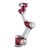
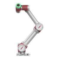
JAKA Zu
®
7 - V1.1 20
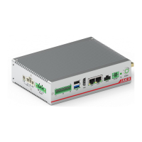
Hardware interfaces are shown below.
24V power
supply
voltage
interface
Positive terminal of 24V voltage
Negative terminal of 24V voltage
When the dry contact is input, the switch can be collected by connecting this
terminal and DI1 to DI8.
8 digital
inputs (DI1 to
DI8)
8 analog
inputs (AI1 to
AI8)
1st way 0~5V voltage input
2nd way 0~5V voltage input
3rd way 0~5V voltage input
4th way 0~5V voltage input
Test output point, can output 5V level, used for test purposes of AI1 ~ AI8.
8 digital
outputs (DO1
~ DO8)
The first relay output, R and L represent the 2 contacts of the relay
The second relay output, R and L represent the 2 contacts of the relay.
The third relay output, R and L represent the 2 contacts of the relay
The fourth relay output, R and L represent the 2 contacts of the relay
The fifth relay output, R and L represent the 2 contacts of the relay
The sixth relay output, R and L represent the 2 contacts of the relay
The seventh relay output, R and L represent the 2 contacts of the relay
The eighth relay output, R and L respectively represent the two contacts of
the relay
 Loading...