Page 26
ENGLISH
Jandy
®
Pro Series, JXi
™
Gas-Fired Pool & Spa Heater
|
Installation & Operation Manual
Do not connect more than two (2) wires to any of the
terminals in the Control System when connecting
peripheral devices. If connecting the heater to the control
system creates this situation, then a Multiplex PCB
kit must be used. Call your distributor or Zodiac Pool
Systems, Inc., to order the kit.
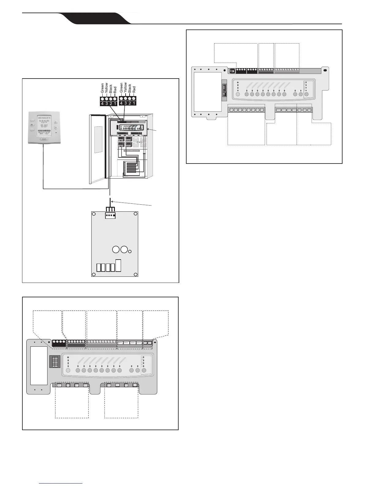
Figure 24. Wiring the JXi to a Zodiac
®
Remote
RESET
SERVICE
TIME OUT
FILTER PUMP
AUX 1
AUX 2
AUX 3
AUX 4
AUX 5
AUX 6
AUX 7
RS6 & RS8 ONLY
RS8 ONLY
HEATER
SOLAR
POOL MODE
SPA MODE
SPA DRAIN
SPA FILL
AUTO
654321
10 9876 54321
4321
4321
To Sensors, etc.
(green terminal bar)
To Remote
(brown terminal bar)
To Controller
(red terminal bar)
GR Y BK R
4 3 2 1
Power Center
Indoor Controller
LXi Control
RS Control
System
Power
Center
Bezel
22 Gauge
4 Conductor
Wire
JXi Control
Figure25. PCBwithrmwareREVMMMorlower
Spa Side
Switch
Sensors and
Heater
JVA Sockets
24 VAC
Relay Sockets
24 VDC
Connection to
Controller:
RS485
Connectors
Relay Sockets
24 VDC
Relay Sockets
24 VDC
Intake
Return
Cleaner
Solar
Solar Pump
Elect Htr
Aux 1
Aux 2
Aux 3
Aux 4
Aux 5
Aux 6
Aux 7
4321
654321
10 9876 54321
RESET
SERVICE
TIME OUT
FILTER PUMP
AUX 1
AUX 2
AUX 3
AUX 4
AUX 5
AUX 6
AUX 7
RS6 & RS8 ONLY
RS8 ONLY
HEATER
SOLAR
POOL MODE
SPA MODE
SPA DRAIN
SPA FILL
AUTO
S1
S2
654321
10 9876 54321
4321
4321
RESET
SERVICE
TIME OUT
FILTER PUMP
AUX 1
AUX 2
AUX 3
AUX 4
AUX 5
AUX 6
AUX 7
RS6 & RS8 ONLY
RS8 ONLY
HEATER
SOLAR
POOL MODE
SPA MODE
SPA DRAIN
SPA FILL
AUTO
Connection to
Controller:
RS485 Connectors
Spa
Side
Switch
Sensors
and
Heater
Relay Sockets
24 VDC
Relay Sockets
24 VDC
JVA Sockets
24 VAC
Aux 1
Aux 3
Aux 2
Aux 4
Aux 5
Aux 6
Aux 7
Intake
Return
Cleaner
Solar
Elect. Htr.
Spare
Figure26. PCBwithrmwareREVNorhigher
If your PCB rmware is REV MMM or lower, connect
via a 2-wire connection. See Section 6.5.2.
IfyourPCBrmwareisREVNorhigher:
1. Turn off the power to both the heater and the
controller.
2 Open the power center enclosure and remove the
front dead panel.
NOTE Only an AquaLink
®
RS System with firmware revision
"N", or higher, will support the heater interface. Refer
to Table 7 and Figures 25 and 26 to determine the
REV of your system's firmware. If it is "N" or higher,
continue with these procedures. If it is MMM or lower,
follow the procedures in Section 6.5.2.
NOTE Only a PDA System with firmware revision 4.1, or
higher, will support the heater interface.
3. Use 22 gauge 4-conductor wire to run between
the heater and the RS control and match the wire
color order (Figure 24).
4. The wires coming from the heater can be
“doubled up” on the red terminal bar with the four
(4) wires from the indoor controller.
NOTE If you need to install more than two (2) wires in each
terminal, order a Zodiac
®
Multiplex PCB Kit, which
includes the Multiplex Board (Zodiac part # 6584).
Never put more than two (2)wires into each of the pins
of the terminal bar.
5. Check all wiring, then apply power to both the
heater and the control system. Verify operation
in either Service or Auto mode. Refer to your
Control System manual for operating instructions.