Model LJ Pool and Spa Heater
Page 11
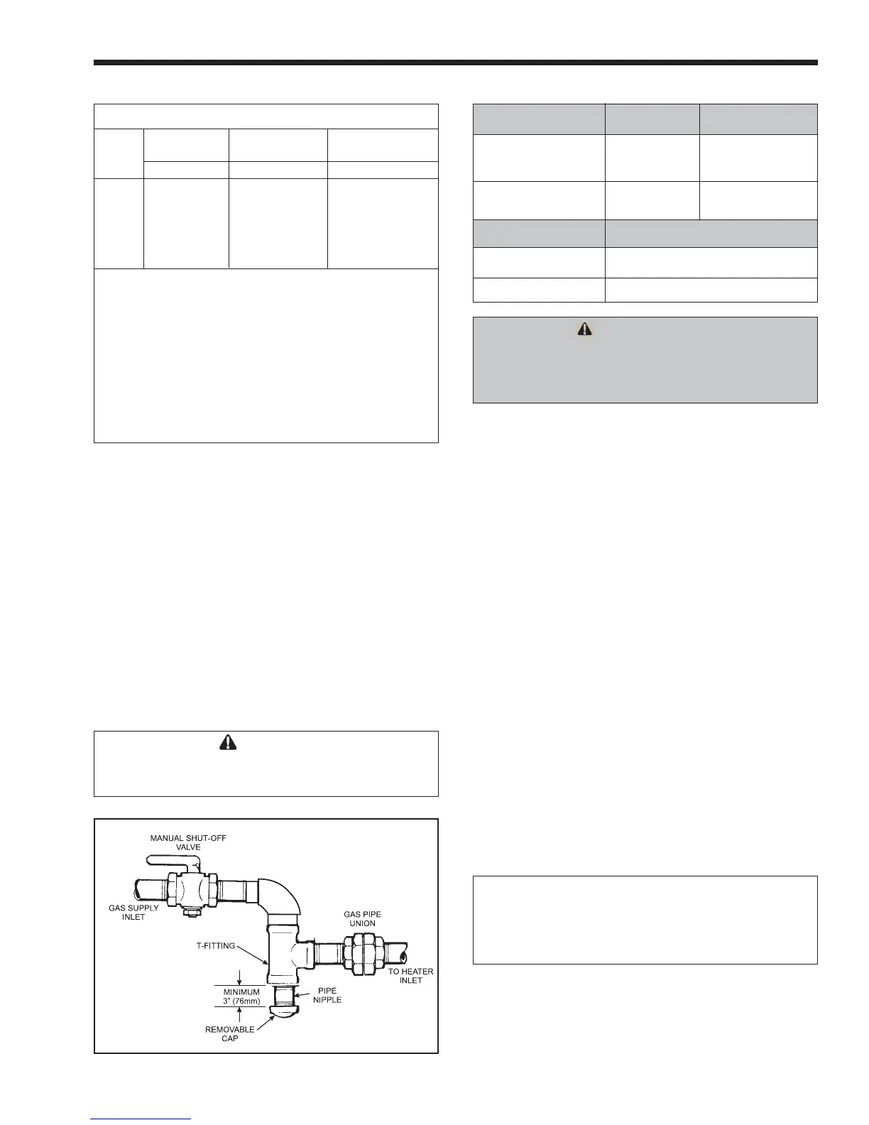
Figure 6. The proper design for a sediment trap / drip leg
plate. Jandy Lite2 LJ heaters, as shipped from
the factory, are certified to operate within the
altitude range indicated on the rating plate. If a
field conversion to a different altitude range
should be necessary, manifold kits are available
for changing the altitude range of the heater. See
Table 1 in section 1.7.1 of this manual to deter-
mine the correct altitude designation for your
heater. Refer to Section 11 “Parts List” to order
the correct part number of the manifold kit
needed. When changing the altitude range of the
heater, be sure to fill out the altitude conversion
label, included in the kit. Apply the label on the
inner panel of the heater, next to the original
rating plate.
CAUTION
Permanent damage to the gas valve will occur
if the following procedures are not followed.
ATTENTION
Vous endommagerez la soupape de gaz si
vous ne respectez pas les procédures
suivantes.
3. Use the figures in Table 4 to size the gas inlet
piping from the gas meter to the heater. Check
all local codes for compliance before installing
the heater.
Table 4. Natural Gas Pipe Size Requirements
Distance from Gas Meter
0-50 feet 50-100 feet 100-200 feet
Heater (0-15 m) (15-30 m) (30-60 m)
Size in. (mm) in. (mm) in. (mm)
125 3/4 (19) 1 (25) 1 (25)
175 1 (25) 1 (25) 1-1/4 (32)
250 1 (25) 1-1/4 (32) 1-1/4 (32)
325 1-1/4 (32) 1-1/4 (32) 1-1/2 (38)
400 1-1/4 (32) 1-1/2 (38) 1-1/2 (38)
Notes:
1. These numbers are for natural gas (0.65 Sp. Gr.) and are
based on 1/2 inch (13mm) water column pressure drop.
Check supply pressure with a manometer, and local code
requirements for variations. For liquefied petroleum gas,
reduce pipe diameter one size, but maintain a 3/4 inch
(19mm) minimum diameter.
2. Check supply pressure and local code requirements
before proceeding with work.
3. Pipe fittings must be considered when determining gas
pipe sizing.
Supply Pressure Minimum Maximum
Natural Gas 5.5 Inches WC 10.0 Inches WC
(1.4 kPa) (2.5 kPa)
LP Gas 10.0 Inches WC 14.0 Inches WC
(2.5 kPa) (3.5 kPa)
Manifold Pressure Nominal
Natural Gas 4.0 Inches WC (1.0 kPa)
LP Gas 9.0 Inches WC (2.2 kPa)
Table 5. Gas Supply Pressure Requirements
4. Install a sediment trap (drip leg) ahead of the gas
controls (see Figure 6). Fit the trap with a
threaded cap which can be removed for cleaning.
5. Install a manual gas shutoff valve for service and
safety. Do not use a restrictive gas cock. DO
NOT USE FLEXIBLE GAS PIPING, it will
restrict the gas flow to the heater.
6. Disconnect the heater and its individual shutoff
valve from the gas supply system during pressure
testing of the system at pressures higher than 1/2
pounds per square inch (psi) (3.45 kilopascals
[kPa]). If the test pressure is equal to or less
than 1/2 psi (3.45 kPa), close the manual shutoff
valve on the heater during the piping pressure
test.
7. If the gas supply pressure is less than required,
check for undersized pipe between the meter and
the heater, a restrictive fitting, or an undersized
gas meter. Gas supply pressures to the heater
are listed in Table 5.
NOTE: The maximum inlet gas pressure must
not exceed the specified value. The minimum
value listed is for the purpose of input
adjustment. Refer to Table 5.
8. Before operating the heater, test the complete
gas supply system and all connections for leaks
using a soap solution. Do not use an open flame.