Model LJ Pool and Spa Heater
Page 15
heater (sizes 125,175 and 250 only), the end
baffles of the heat exchanger must be removed.
There are two baffles covering part of the front
and rear tubes of the heat exchanger. Each
baffle is held in place by two screws which
mount to the top of the combustion chamber wall.
Remove the screws and the baffles before
attempting to lift the heat exchanger out of the
heater (see Figure 12).
CAUTION
The heat exchanger is heavy. It may be
necessary to have help lifting the heat
exchanger out and replacing it.
ATTENTION
L’échangeur de chaleur est lourd.Il peut être
nécessaire d’avoir besoin d’aide pour enlever et
remplacer l’échangeur de chaleur.
12. Lift the heat exchanger assembly out of the
heater. Reinstall heat exchanger 180 degrees
(inlet/outlet header left) from it's original position.
13. After replacing the heat exchanger into the
heater, the end baffles must be replaced. Each
one is held in place by two screws which mount
to the top of the combustion chamber wall.
Reinstall the baffles on the front and rear of the
heat exchanger before continuing with the
"Reversible Water Connections" procedure.
14. Remove pressure switch retainer (plastic cable
clamp) from the inner panel (allow pressure
switch to float).
15. Reroute pressure switch tube and thermostat
bulb assembly through hole in left side of vesti-
bule cover in reverse order. Relocate the pres-
sure switch tube and temperature sensor through
the open side of the vestibule.
16. Reinstall the temperature sensing bulb in the
header, and fasten it with the retainer bracket
and screw.
17. Reinstall the compression fitting at the end of the
pressure switch tube into inlet/outlet header and
tighten the fitting.
18. Route the white wiring from the high limit
switches beside the heat exchanger and down to
the original location following the pressure switch
tubing. Secure white wires to the pressure switch
tube with plastic wire ties.
19. Connect the white wire labeled PS to the pres-
sure switch and the other white wire to its
original location on the fusible link.
20. Reinstall the drain plugs and tighten securely.
Replace jacket/plug grommets.
21. Install the flue collector assembly. Be sure the
front and rear panels of the flue collector are
installed into the grooves on the front and rear
combustion chamber heat shield panels. Be sure
the sheet metal panels are not pinching any
wires.
22. Attach the flue collector hold down clamps to the
clips located under the two center header bolts.
23. Replace the gap closures and tighten the screws
securely. Be sure to replace the insulation,
completely covering the temperature sensor.
Insulation must be a minimum of 1" thick.
24. Double-check to make sure the wiring is not
pinched against sharp edges, or resting on the
flue collector assembly.
25. Reinstall rain shield assembly.
26. Replace the top assembly. Make sure the tabs
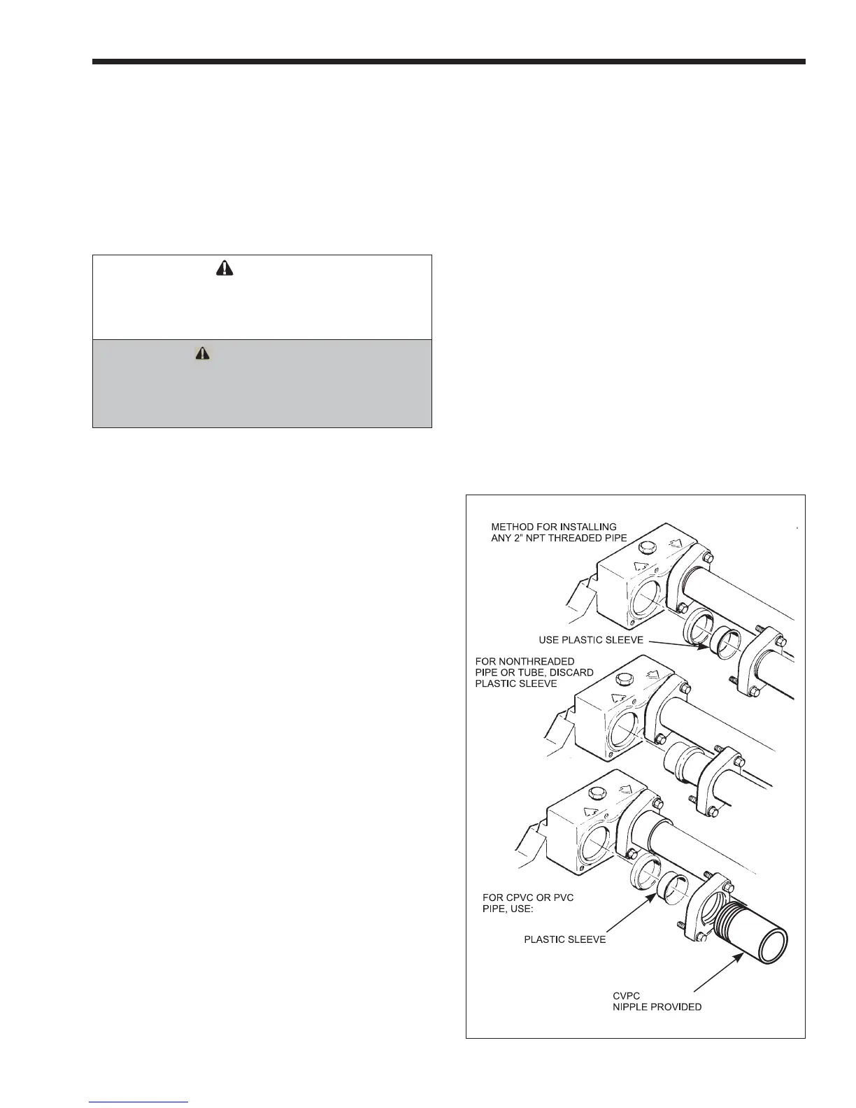
Figure 13. Piping installation