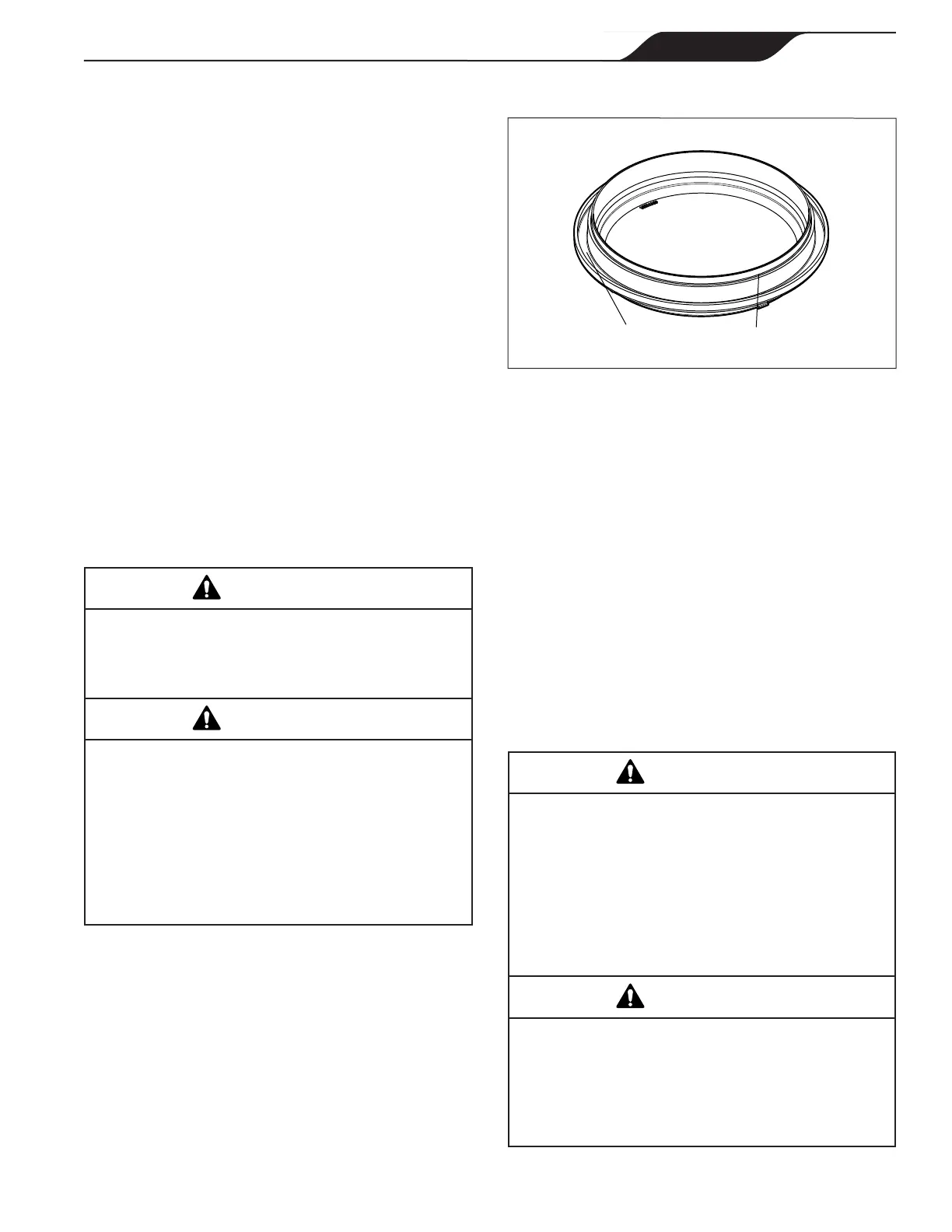
2. Place the blue o-ring on the step located ¼"
from the bottom of the lid. See Figure 5.
Figure 5. Placement of Blue Pressure Test O-ring
Upside Down View of Bottom of Lid
Step where
O-ring is Seated
Groove where
Seal is Seated
3. Make sure that the o-ring is properly seated. It
helps to “place” the o-ring on the step rather
than to “roll” it on. That prevents it from rolling
off.
NOTE The blue o-ring sits approximately ¼" away from the
seal. See Figure 5.
4. Carefully install the lid, making sure that the
blue pressure test o-ring sits in the housing
without “binding” or “rolling” off.
5. Following the markings on the locking ring,
align ‘START’ markings with the ports and
turn clockwise until ‘LOCKED’ markings
align with the ports. Do not tighten past the
‘LOCKED’ marking.
3.3.1.3 Conduct Pressure Test
When pressure testing a system with water, air
isoftentrappedinthesystemduringthelling
process. This air will compress when the system is
pressurized. Should the system fail, this trapped air
can propel debris at a high speed and cause injury.
Every effort to remove trapped air must be taken,
includingopeningthebleedvalveonthelterand
looseningthepumpbasketlidonthelterpump
whilellingthepump.
WARNING
Trappedairinsystemcancauselterlidtobe
blown off, which can result in death, serious per-
sonal injury, or property damage. Be sure all air is
properly out of system before operating. DO NOT
USE COMPRESSED AIR TO PRESSURE TEST
OR CHECK FOR LEAKS.
WARNING
3.3.1 Replace Blue Pressure Test O-ring if
Necessary
If you open the pump lid before conducting the pressure
test, the blue o-ring may fall out. If this happens, you
will need to install it on the lid again before conducting
pressure testing.
There is a risk of damage to the blue o-ring during re-
installation. If you damage it when trying to re-install
it, you will need to order a new blue pressure test o-ring
(R0479000) before you begin conducting the pressure
test.
These instructions describe the proper procedures for
replacing, using, and disposing of the blue o-ring.
These instructions must be followed exactly. Read
through the instructions completely before starting
the procedure.
3.3.1.1 Remove Pump Lid
1. Make sure that the pump is turned off.
2. Make sure that the switch to the circuit breaker
that powers the pump motor is turned off.
Turn off the pump and the main breaker in the
pump electrical circuit before starting the procedure.
Failure to comply may cause a shock hazard,
resulting in severe personal injury or death.
WARNING
Duetothepotentialriskofre,electricshock,or
injuries to persons, Jandy Pumps must be installed
in accordance with the National Electrical Code
®
(NEC
®
),intheUSA,ortheCanadianElectrical
Code (CEC
®
)inCanada.Allapplicablelocalcodes
must also be followed.
The NEC may be obtained by contacting the
National Fire Protection Association
®
(NFPA
®
)at
1-800-344-3555 or 1-617-770-3000.
WARNING
3. Make sure all necessary isolation valves are
closed to prevent pool water from reaching the
pump.
4. Following the markings on the locking ring,
turn the ring counter-clockwise until the
‘START’ markings align with the ports.
5. Carefully remove the lid with locking ring.
3.3.1.2 Replace Blue O-ring
1. Turn the lid with locking ring upside down and
place it on a stable surface.
Page 11
ENGLISH
Jandy
®
Stealth
™
Pumps
|
Operation Manual