24
UMG 96RM-P/-CBM
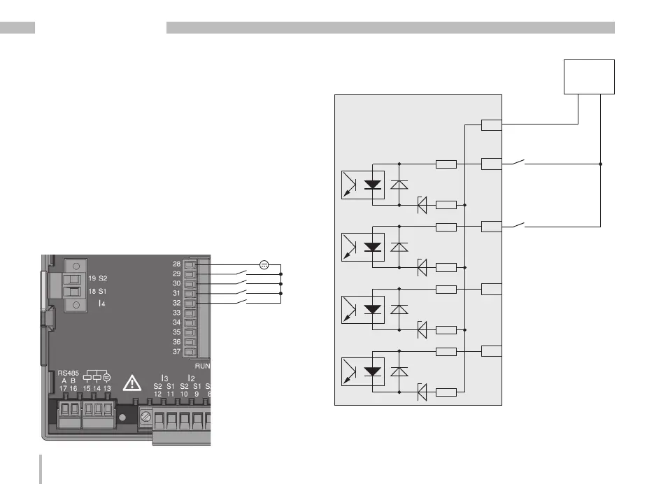
Digital inputs
The UMG 96RM-P and UMG96RM-CBM have 4 digital
inputs, each of which can have a signal transducer
connected.
On a digital input an input signal is detected if a voltage
of at least 10V and maximum 28V is applied and where
a current of at least 1mA and maximum 6mA flows
at the same time. Wiring longer than 30m must be
screened.
Note the correct polarity of the supply voltage!
-
+
-
+
24V DC
S1
S2
External
auxiliary voltage
28
29
30
31
32
2k21
2k21
2k21
2k21
2k21
2k21
2k21
2k21
Digital
Input 1
Digital
Input 2
Digital
Input 3
Digital
Input 4
UMG 96RM-P/-CBM
Digital inputs 1-4
Fig. Connection
example for digital
inputs.
Fig. Example for the connection of external switch
contacts S1 and S2 to digital inputs 1 and 2.

 Loading...


