19
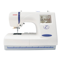
MC300E
Connector Connection Diagarm
Please see the following connector connection diagram for the printed circuit board A.
51 2 3 4
11
12
13
14
10
6
7
8
9
Touch panel
LCD Harness
Printed circuit board F( Black )
Bobbin winder sensor ( Blue )
Upper shaft sensor ( Black )
Thread detection sensor ( Red )
Presser foot lifter sensor ( Red )
12
8
9
10
11
13
14
Switching power supply ( White )
X- Motor ( Blue )
Y- Motor ( White )
Solenoid for thread tension ( Red )
Lamp ( White )
Inverter ( White )
DC Motoe ( White )
5
1
2
3
4
6
7

 Loading...