AAA-055-00138 Rev. 1/14/15
Jaylor Owner Manual - 3 - Mini Mixer Models
TABLE OF FIGURES
Figure 1 - A50 Safety Decal Locations for Standard Models ....................................................... 13
Figure 2 - A100 Safety Decal Locations for Standard Models ..................................................... 14
Figure 3 - Self-Propelled ‘Warning’ Decal .................................................................................. 15
Figure 4 - General ‘Warning’ Decal ............................................................................................ 15
Figure 5 - ‘Pinch Point Hazard’ Decal ........................................................................................ 16
Figure 6 - ‘Rotating Auger Hazard’ Decal ................................................................................... 16
Figure 7 - ‘High Pressure Fluid Hazard’ Decal ........................................................................... 16
Figure 8 - A50 Safety Decal Locations for CE Models ................................................................ 17
Figure 9 - A100 Safety Decal Locations for CE Models .............................................................. 18
Figure 10 - ‘Rotating Auger Hazard and Rotating Knives’ Decal ................................................. 19
Figure 11 - ‘Remove Ignition Key Before Servicing, Maintaining, or Adjusting the Vertical Mixer’
Decal ................................................................................................................................. 19
Figure 12 - ‘Wear Ear Protective Gear When Operating the Vertical Mixer’ Decal ...................... 19
Figure 13 - ‘Wear Safety Boots When Operating, Servicing, Maintaining, or Adjusting the Vertical
Mixer’ Decal ....................................................................................................................... 19
Figure 14 - ‘Keep Safe Distance From Machine and Keep Children Out or Range’ Decal ........... 19
Figure 15 - ‘Read Manual Before Operating, Maintaining, or Adjusting the Vertical Mixer’ Decal 19
Figure 16 - ‘Do NOT Drive on Steep Slopes’ Decal .................................................................... 19
Figure 17 - ‘Keep Safe Distance From Hot Surfaces’ Decal ....................................................... 19
Figure 19 - A50 Self-Propelled Mixer Components .................................................................... 20
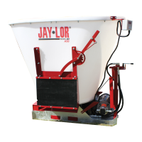
Figure 20 - A50 Stationary Mixer Components ........................................................................... 22
Figure 21 - A50 Skid Steer Mixer Components .......................................................................... 23
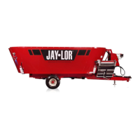
Figure 22 - A50 Trailer Mixer Components ................................................................................ 24
Figure 23 - A50 Truck Mounted Mixer Components ................................................................... 25
Figure 24 - A100 Self-Propelled Mixer Components................................................................... 26
Figure 25 - A100 Stationary Mixer Components ......................................................................... 28
Figure 26 - A100 Trailer Mixer Components............................................................................... 29
Figure 27 - A100 Truck Mounted Mixer Components ................................................................. 30
Figure 28 - A50 and A100 Scale Mounting Bracket Arm Adjustment .......................................... 33
Figure 29 - A50 and A100 Self-Propelled Speed/Direction Control Pedal ................................... 34
Figure 30 - A50 and A100 Self-Propelled Steering ..................................................................... 35
Figure 31 - Trailer Coupler Positions.......................................................................................... 38
Figure 32 - Lug Tread Tire ......................................................................................................... 38
Figure 33 - Truck Mounted Model Tie-Down Bracket Locations .................................................. 39
Figure 34 - A50 Skid Steer Model Transportation ....................................................................... 40
Figure 35 - Typical Total Mix Ration (TMR) Achieved in Mixing Chamber................................... 44
Figure 36 - Imperial Bolt Specifications ...................................................................................... 50
Figure 37 - Metric Bolt Specifications ......................................................................................... 51
Figure 38 - Auger Support Bushing Grease Locations ............................................................... 52
Figure 39 - A50 and A100 Self-Propelled Steering Chain and Sprocket Lubricate Location ........ 53
Figure 40 - A50 and A100 Self-Propelled Steering Shaft Support Bearings Grease Locations .... 53
Figure 41 - A50 and A100 Self-Propelled Steering Assembly Grease Location .......................... 54
Figure 42 - A50 and A100 Self-Propelled Speed/Direction Control Bushing Lubricate Location .. 54
Figure 43 - A50 and A100 Trailer Hub Grease Location ............................................................. 55
Figure 44 - A50 Skid Steer Model Caster Grease Location ........................................................ 55