12 - 8
Fault Finding
up to machine no. 751011
Machine moves when drive control is in neutral.
This may be caused by the neutral setting of the pump being
incorrect but before assuming this check that the joystick
spools are not sticking and are being correctly operated by
the joystick lever.
!!
WARNING
The following procedure requires the machine to be
disabled (wheels raised off the ground, work function
disconnected etc.) while the work is carried out.
HYD 8-1/1
Place the machine safely onto blocks, so that all four wheels
are clear of the ground. Ensure that the machine is stable.
Position the operator’s seat facing forwards so that the
brakes are released.
Start engine and note which pair of wheels is turning. This
will indicate which pump is not returning to neutral. Note
that pump P1 (nearest the engine) feeds the left hand motors
and pump P2 the right hand motors.
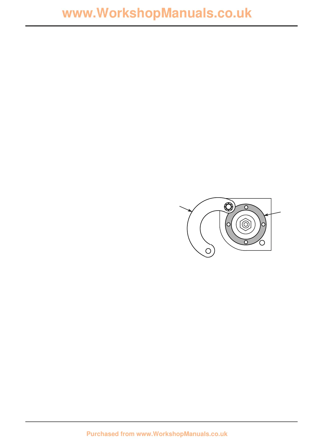
The neutral adjustment can be made by rotating the outer
adjustment ring E on each pair of servo units. Note that any
adjustment to one servo unit must be countered by an equal
adjustment, in the opposite direction, of the other servo unit
of the same pump.
Travel Speed
The maximum speed of the machine should be checked
following the above adjustments. This involves raising the
machine off the ground and checking the wheel speeds
using a stroboscopic meter.
Note that excessive wheel speed may result in cooling
problems as the hydraulic oil may overheat.
!!
WARNING
The following procedure requires the machine to be
disabled (wheels raised off the ground, work function
disconnected etc.) while the work is carried out.
HYD 8-1/1
Place the machine safely onto blocks, so that all four wheels
are clear of the ground. Ensure that the machine is stable.
Position the operator’s seat facing forwards so that the
brakes are released.
Remove one locking plate screw and slacken the other
screw then swing the locking plate F clear. Adjust as
outlined in the following table. Refer to illustration on
previous page.
Wheel Movement Servo units to be adjusted
R. H. forwards Screw B out and A in
R. H. backwards Screw A out and B in
L. H. forwards Screw C out and D in
L. H. backwards Screw D out and C in
Turn each adjustment ring E one quarter turn at a time and
recheck wheel movement. Always turn one adjustment ring
out before turning the opposite ring in.
When adjustment is complete, re-assemble locking plates
and re-stake.
Stick a piece of reflective tape on a wheel rim. Start the
engine and run at maximum speed then operate the drive
control. Measure the speed of wheel rotation in each
direction which should be 81 rev/min. An allowance of 2%
above this figure is permissible. Check the speed of the
wheels on the opposite side of the machine.
If necessary the appropriate adjusting screws should be
screwed in
1
/2
turn at a time until the correct wheel speed is
achieved. Stop the engine while adjustment is carried out.
If the left hand wheels are rotating too fast screw in
adjusters C and A (see illustration on previous page). Both
adjusters must be turned by equal amounts to maintain
straight line travel.
If the right hand wheels are rotating too fast screw in
adjusters D and B by equal amounts.
Section E Hydraulics
9803/8550
Section E
12 - 8
Issue 1
Pumps
E
F