Section E Hydraulics
9803/8550
Section E
Pumps
12 - 11
Hydrostatic Pump
from machine no. 751012
Charge/Anti-stall Valve
Dismantling and Assembly
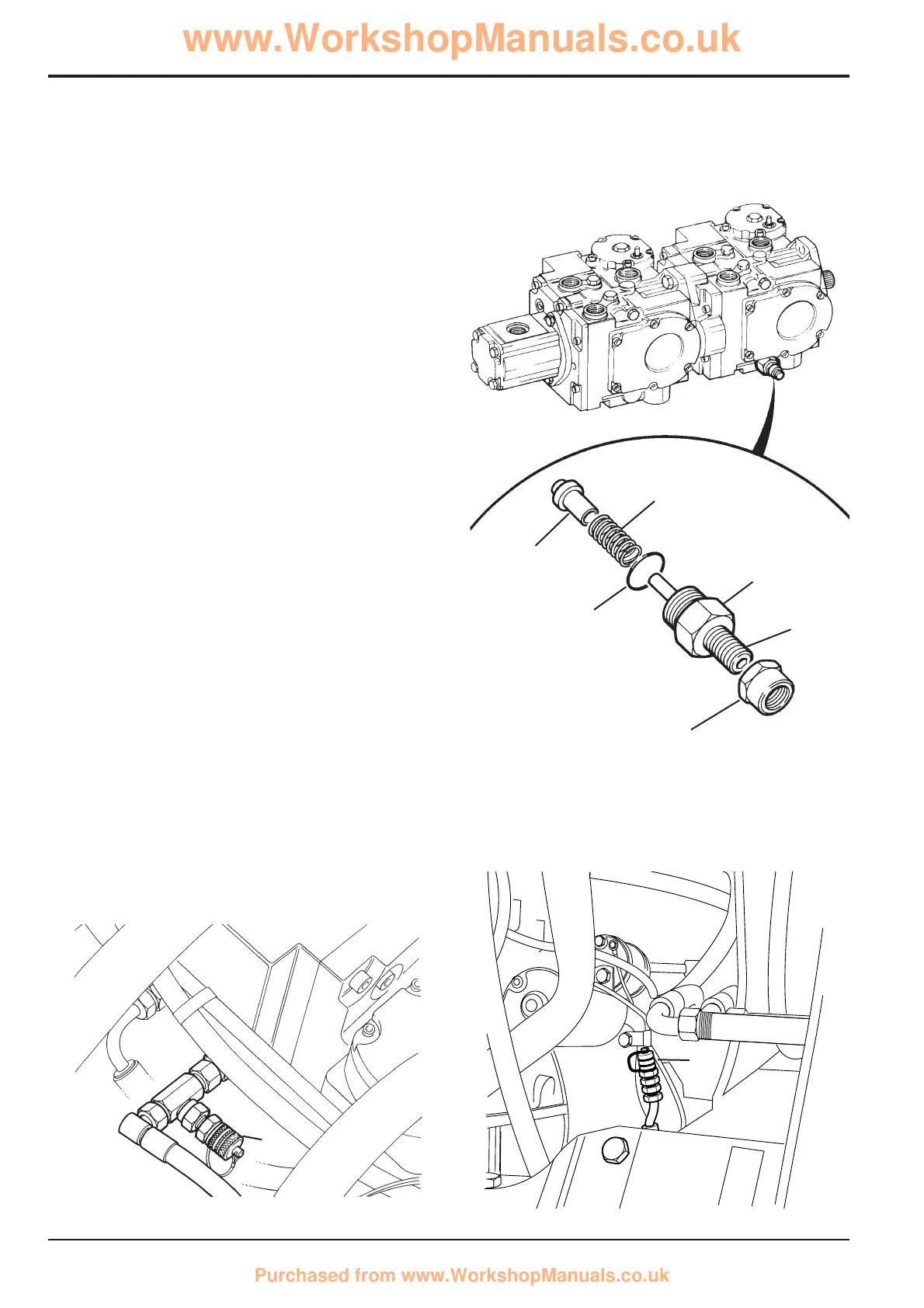
1 Mark the plug 1, locknut 2 and the pump body so as to
approximately maintain the original adjustment.
2 Loosen locknut 2 and unscrew plug 1 from pump body.
Remove O-ring 3 from plug 1 and discard O-ring.
3 Remove spring 4 and poppet 5 from pump body.
4 Inspect poppet 5 and mating seat in pump body for
damage. Renew as necessary.
5 Install a new O-ring 3 on plug 1.
6 Fit poppet 5 and spring 4 into pump body.
7 Screw plug 1 complete with locknut 2 into pump body
to align with the marks made during disassembly.
Tighten the locknut.
8 Check the charge pressure and adjust as necessary.
Charge Pressure Checking and Adjustment
1 Stop engine. Connect a 0 - 40 bar (0 - 600 lb/in
2
, 0 - 42
kg/cm
2
) pressure gauge into the test point which up to
machine no. 751715 is situated underneath the pump
as shown at X. From serial no. 751716 the test point is
positioned at the rear of the left hand side of the engine
as shown at Y.
2 Start engine and check pressure is as specified in
Technical Data.
3 If the pressure is not as specified, stop the engine.
Unscrew locknut 2 and turn adjuster Z
1
/4 turn at a time
(clockwise to increase pressure) then re-tighten
locknut. Start engine and re-check pressure. Continue
procedure until pressure is correct then remove
pressure gauge.
12 - 11
Issue 3*
S244920
4
3
2
5
1
Z
S246240
X
*
348890
Y