JCB EcoMAX Engine Installation Manual
© JCB Power Systems Ltd. 320/A9164-1 Page 45 of 64
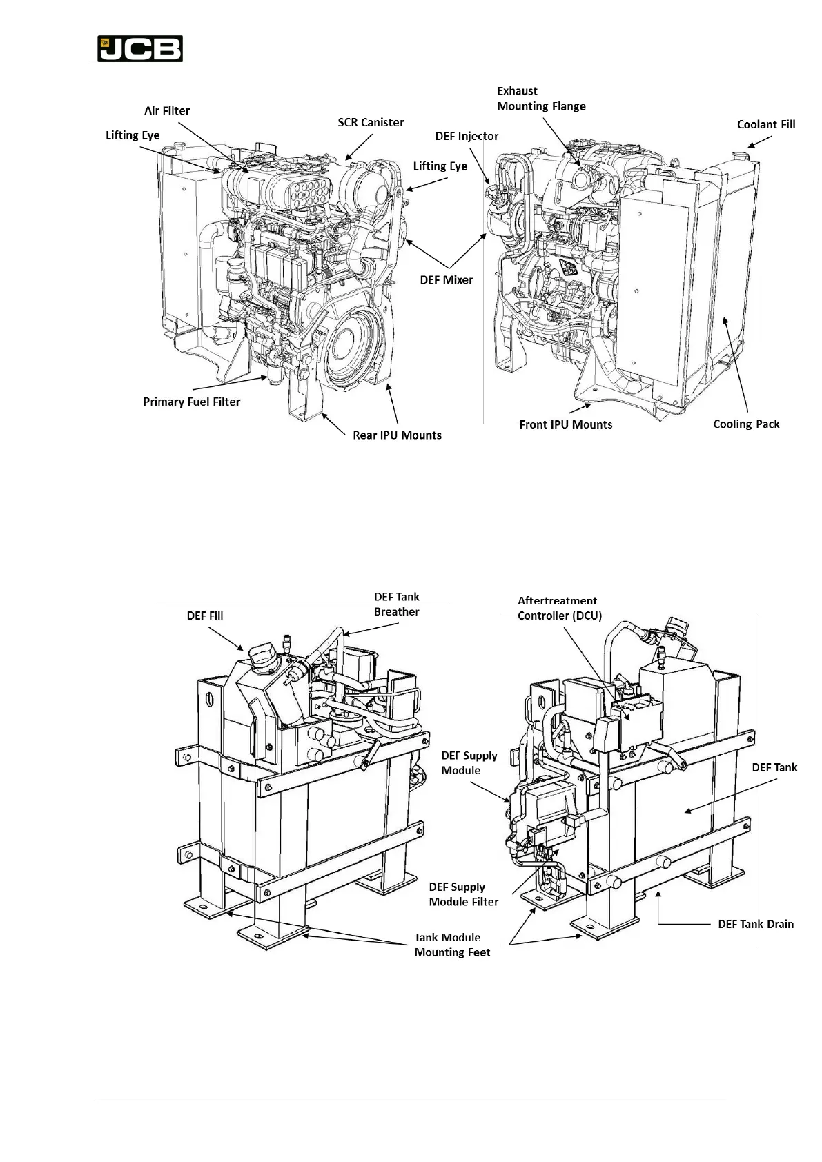
Figure 13 shows the aftertreatment components mounted to the tank module that need to
have suitable access for servicing. Particular attention must be given to the removal of the
filter from the supply module, DEF tank drain and the tank breather filter on the end of the
breather pipe.
Figure 13: Position of regularly accessed items on the DEF Tank Module
Figure 12: Position of regularly accessed items on the IPU