P/N 960-000167R_Rev. 1 {EDP #214645} © 2013, Japan CashMachine Co., Limited
DT-300™ Series Download Tool Operator Integration Guide
3. When removing the SD Card from the DT-300™,
push in on the SD Card in the insertion direction
once and then pull the SD Card out of the DT-
300™ Device.
DIP Switch Setting
DIP Switch Settings are necessary to communicate
with the DT-300™ and a Validator. Refer to “Com-
patibility” on page 14 of this Guide for proper DIP
Switch Settings related to each Validator Model.
Functions
The following two (2) Functions exist for the DT-
300™ Device:
B
OOTLOADER
The Bootloader Function contains the following
two (2) Modes:
• “BlueWaveDX Firmware Update Mode” to
u
pgrade the Firmware in the DT-300™ Device
• “BlueWaveDX EEPROM Update Mode” to
update the EE
PROM data within the DT-300™
Device.
M
AIN
A
PPLICATION
(N
ORMAL
M
ODE
)
MainApplication (Normal Mode) contains the
following two (2) Functions:
• “Firmware Update Function” to upgrade the
Firmware within
the Validator
• “Acceptance Log Function” to receive and
dis
play the Acceptance Log.
Boot Mode
When the DT-300™ is initialized, three (3) Modes
will be available. Select one Mode by using the
Direction Key Button to move and select to the
desired Operational Mode (See Table 5).
Authentication
When the MainApplication is booting, the DT-
300™ will authenticate itself with the information
on the SD Card.
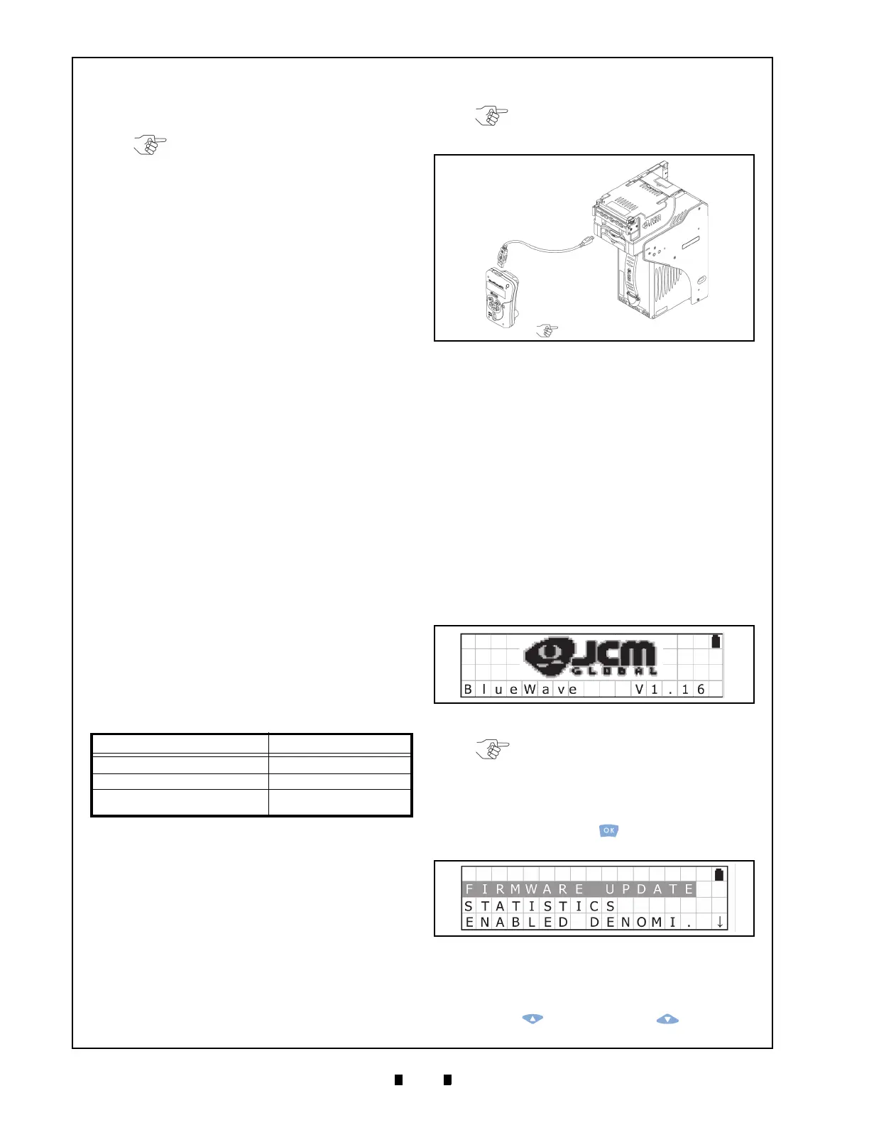
USB Cable Connection
Perform the following steps to connect a Power-
Supplied Validator to the DT-300™ Device:
1. Connect the USB Cable A Terminal to the DT-
300™ Unit’s Connector “A” Port (See Figure 9
a).
2. Connect the USB Cable B or Mini-B terminal to
th
e Validator’s USB Port (See Figure 9 b).
Operation Procedures
(MainApplication)
This portion provides each MainApplication
procedure of the DT-300™ Device Operation.
F
IRMWARE
U
PDATE
F
UNCTION
To update the Firmware of the Validator, proceed
as follows:
1. Make sure that the SD Card contains the required
Software Data File (Refer to “Software Data File”
on page 13 of this Guide for details regarding
selection of the correct So
ftware Data File).
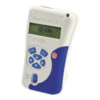
2. Turn the DT-300™ Power Switch ON; an SD
Card check will begin as shown in Figure 10.
3. Select “FIRMWARE UPDATE” Function on the
Function Selection Screen shown in Figure 11,
and press the
OK Key to begin the Firmware
Erase process.
4. Connect the USB Port of the V
alidator to the DT-
300™ Device using a proper USB Cable.
5. Select the download File desired by pressing the
UP Key or the DOWN Key , and then
Table 5 B
oot Mode Selection
Mode Direction Key Button
DT-300 Firmware Update Mode UP + DOWN
DT-300 EEPROM Update Mode LEFT + RIGHT
Normal Mode (MainApplication)
N/A (except the other
combinat
ions)
NOTE: Do NOT push the SD Card in by
using excessive force!
NOTE: Refer to “Compatibility” on
page 14 of this Guide to select the “B” or
“Mini-B” Connection Terminal.
NOTE: Validator power must be supplied.
Figure 9 Cable Connection
Figure 10 SD Card Confirmation Screen 1
NOTE: Product specifications (e.g.,
version) may vary from illustrations, and
are subject to change without notice.
Figure 11 Function Selection Screen 1