P/N 960-000167R_Rev. 1 {EDP #214645} © 2013, Japan CashMachine Co., Limited
DT-300™ Series Download Tool Operator Integration Guide
B
ACKLIGHT
C
ONTROL
The DT-300™ Device contains the following Back-
light Control Functions:
Bootloader: – The Backlight is always lit.
MainApplication: – The Backlight is lit by
pressing any Function Key or by booting the
MainApplication (after a short delay). It is
extinguished automatically, following a delay.
S
OFTWARE
D
ATA
F
ILE
Table 13 lists the Software Data File information.
R
ECEIVED
L
OG
F
ILE
Table 14 lists the received Log File. The received
Log File is always created as a new File.
F
IRMWARE
F
ILE
Table 15 lists the MainApplication Firmware File
presently written in the DT-300™ Device
Memory.
EEPROM D
ATA
F
ILE
Table 16 lists the saved File written into the
EEPROM of the DT-300™ Device.
Table 13 Software Data File Information
Item Description
File Name
xxxxxxxxx.COM
*
*. An arbitrary name is present with a “COM” extension.
File Contents Download Software Data
Table 14 Received Log Files
Item Description
File Name
UBA: mmm_ssssssssssss_nnnn.DAT
TBV/iVIZION/iPRO:
mmm_ssssssssssss_
nnnn.LOG
mmm: Model Name
ssssssssssss: Serial Number (12-digit
decimal. If the number was not read, none.)
nnnn: Number (4-digit decimal)
e.g., “UBA_0001.DAT”, “iPRO1234.LOG”
*
†
NOTE: The Backlight is lit each time a Key is
pressed; however, there is no specific
Function Key that controls it.
File Contents
Binary Format File written Log Information.
Save the Data received from the Device
without pr
ocessing.
Time Stamp Fixed
*. Creating file name with valid small Serial Numbers.
†. An error will occur once a “9999” Serial Number is exceeded.
Table 15 Existing Firmware File
Item Description
File Name
BWDXFyyxx.hex
*
*. “yyxx” indicates the Version Number (e.g., Version 1.23=0123).
File Contents Motorola S Type Format Program File
Table 16 EEPROM Data File Information
Item Description
File Name BWDXINFO.INF
File Contents Text Format File written data for the EEPROM
Table 14 Received Log Files (Continued)
Item Description
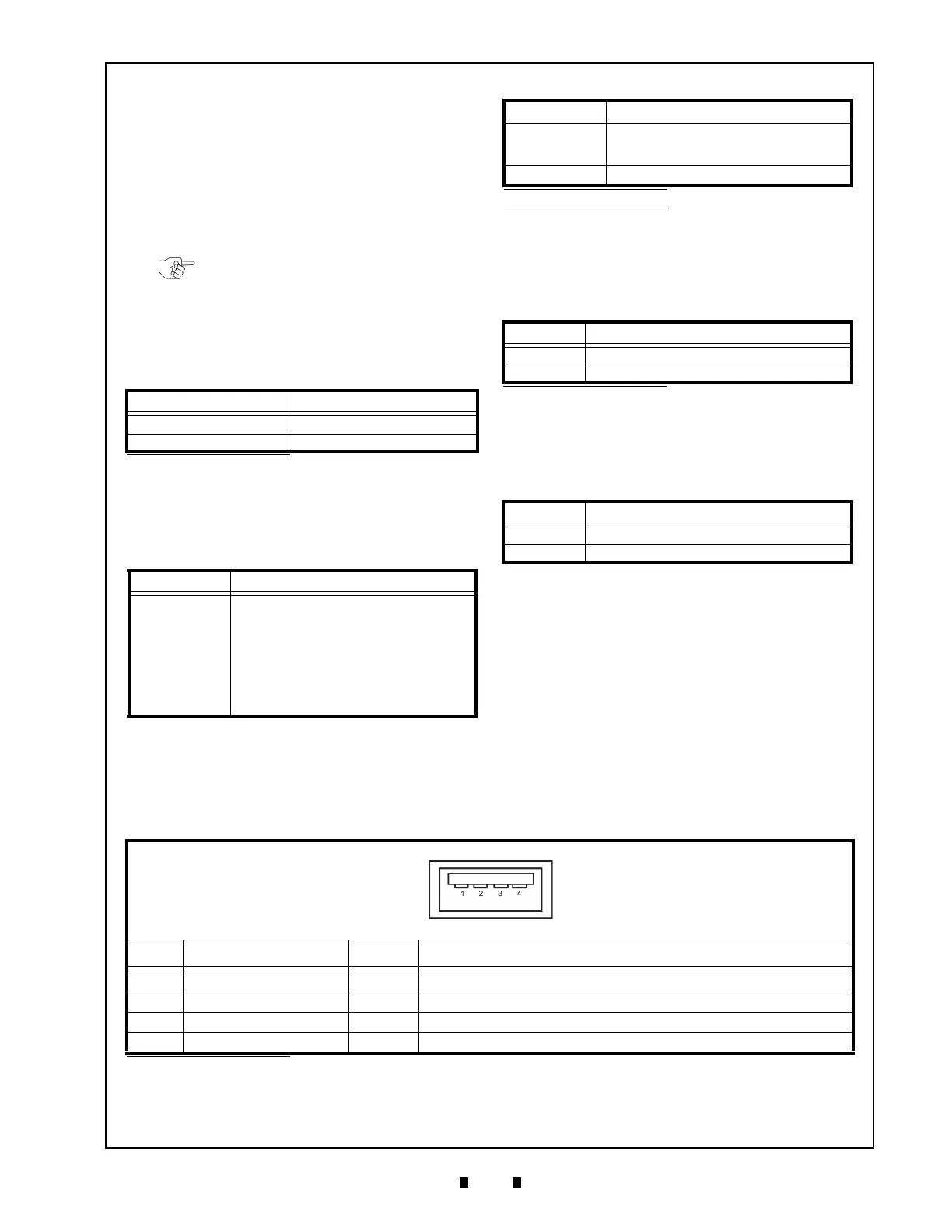
Table 17 DT-300 USB Type “A” Pin Assignments
DT-300 USB Type “A” Connector
UBA-4R-D14T-4D (JST)
Pin No. Signal Name
I/O
*
Function
1
VBUS OUT +5V
2 DM IN/OUT USB Data-
3 DP IN/OUT USB Data+
4 Ground -
Power Ground
*. I/O (Input/Output) Terminals as viewed from outside the DT-300™ Device.
7 CONNECTOR PIN ASSIGNMENTS
Table 17 lists the DT-300™ USB “Type A” Connector Pin Assignments, respectively.
 Loading...